1 > cabinet icon – Austin Hughes X-800 Smartcard Handle User Manual
Page 42
www.austin-hughes.com
UM-X-ISM-Q414V3
P.37
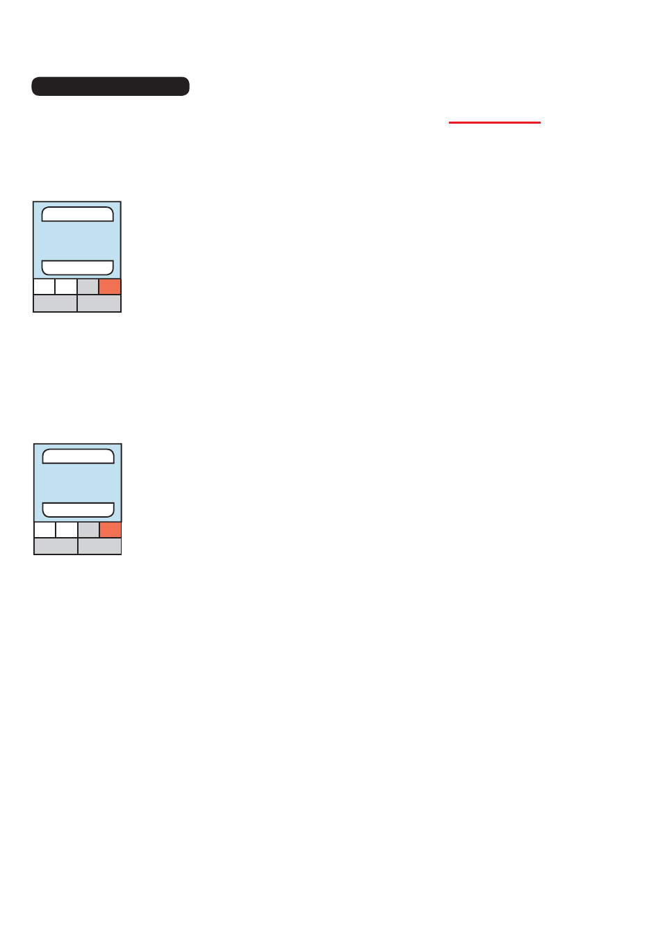
< 8.1 > Cabinet Icon
- show PDU status ( P1, P2, P3, P4 )
- if PDU is enabled & connected, P icon in WHITE color
- if PDU is enabled BUT disconnected, P icon in
RED
color
- if PDU is on alarm status, P icon also in
RED
color
- if PDU is disabled, P icon in
GREY
color
- show Fan unit status ( F1, F2 )
- if Fan unit is enabled & connected, F icon in WHITE color
- if Fan unit is enabled BUT disconnected, F icon in
RED
color
- if Fan unit is on alarm status, F icon also in
RED
color
- if Fan unit is disabled, F icon in
GREY
color
- show TH sensor status ( S1, S2 )
- if TH sensor is enabled & connected, S1, S2 icon in WHITE color
- if TH sensor is enabled BUT disconnected, S1, S2 icon in
RED
color
- if TH sensor is on alarm status, S1, S2 icon also in
RED
color
- if TH sensor is disabled, S1, S2 icon in
GREY
color
- show smoke & shock sensor status ( S3, S4 )
- if smoke & shock sensor is enabled & connected, S3, S4 icon in WHITE color
- if smoke & shock sensor is on alarm status, S3, S4 icon also in
RED
color
- if smoke & shock sensor is disabled, S3, S4 icon in
GREY
color
- show water sensor status ( S5, S6 )
- if water sensor is enabled & connected, S5, S6 icon in WHITE color
- if water sensor is on alarm status, S5, S6 icon also in
RED
color
- if water sensor is disabled, S5, S6 icon in
GREY
color
Cabinet icon has two layers, the layer one by default shows on all control area under view mode
for status monitoring. User can click cabinet icon to switch to layer two.
Cabinet Icon layer
Layer one
Layer two
Cabinet
0014
S1 S2 S3 S4
S5 S6
Cabinet
0014
P3 P4
F2
P2
F1
P1