31 electrical line installation, Figure 20, In-wd01 inglenook blower wiring diagram – American Energy Systems Inglenook User Manual
Page 31
Version: 7.1
31
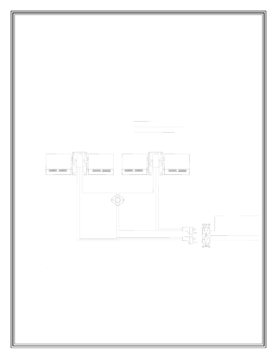
ELECTRICAL LINE INSTALLATION
120 VOLTS AC FOR BLOWER SYSTEM
The Inglenook blower system requires a 120-volt alternating current, 15-ampere, 60-Hertz power
supply circuit. Figure 20 shows the basic electrical diagram for the Inglenook’s blower system.
CAUTION: Moving parts may cause Injury. Do not operate the Inglenook with its lower grill
open.
FIGURE 20
IN-WD01
INGLENOOK BLOWER
WIRING DIAGRAM
PP-12
110 DEGREE HEAT SENSOR
P-350
RHEOSTAT 200, NO ON/ OFF SWITCH
PP-1158 INGLENOOK
BLOWER MOTOR
PP-1157
ELECTRICAL OUTLET
GREEN TO GROUND ON
BLOWER HOUSING
PP-988
POWER CORD
PP-1158 INGLENOOK
BLOWER MOTOR
PP-988
POWER CORD
BLACK
WHITE TO NEUTRAL
GREEN TO GROUND
BLACK TO POWER
BLACK
BLACK
BLACK
BLACK
GREEN TO GROUND ON
BLOWER HOUSING
WHITE
WHITE
- MagnuM Countryside (44 pages)
- MagnuM Countryside (39 pages)
- MF3513S Fuel Stirrer (2 pages)
- MF3514 Fuel Stirrer Drive Shaft (1 page)
- MF3522 Door (2 pages)
- MF3540 Fuel Stirrer Motor (2 pages)
- MF3542 Exhaust Blower (3 pages)
- MF3553 Auger Inspection (1 page)
- MF3573 Auger Motor (2 pages)
- MF3650 Exhaust Blower (3 pages)
- P7554 Brick Board (1 page)
- BC2077 Door (3 pages)
- BC2500 Auto Ignition System (2 pages)
- BC3525 Grill (1 page)
- BC3555 Grill (1 page)
- BC7000 Auger Housing (9 pages)
- MF3626 Door Handle (3 pages)
- MF3642 DC Fan Blade - Exhaust Blower (2 pages)
- RP2062 DC Wire Harness (2 pages)
- RP2063 AC Wire Harness (2 pages)
- RT080 (2 pages)
- MagnuM Baby Countryside (43 pages)
- MagnuM Baby Countryside (42 pages)
- MagnuM Winchester (52 pages)
- MagnuM Winchester (49 pages)
- MagnuM Winchester (51 pages)
- CF25 Room Fan Blower (2 pages)
- P6115 Wire Harness (2 pages)
- MagnuM 6500 (44 pages)
- MagnuM 6500 (45 pages)
- MagnuM 7500 (43 pages)
- MagnuM T40 (50 pages)
- MagnuM T40 (19 pages)
- MagnuM T40 (32 pages)
- MagnuM T40 (31 pages)
- MagnuM ZC (5 pages)
- CF-2200 Door (1 page)
- NPS-1005-N-7 Control Panel (11 pages)
- PP-1030-LR Wire Harness (3 pages)
- PP-1502 Auger Weldment (2 pages)
- Country Flame Little Rascal (35 pages)
- Country Flame Little Rascal (37 pages)
- Harvester (44 pages)
- Harvester (57 pages)
- Crossfire Flex (58 pages)