Bios exit setup screen, Figure 4-7 – ADLINK CoreModule 430 User Manual
Page 51
Chapter 4
BIOS Setup
CoreModule 430
Reference Manual
45
GPCS Configuration
•
GPCS0 Function – [Enabled; Disabled]
•
GPCS1 Function – [Enabled; Disabled]
Redundancy Control Configuration
•
Dual Port 4 KB SRAM – [Enabled; Disabled]
•
SB Serial Port 9 – [Disabled; 3F8; 2F8; 3E8; 2E8; 10]
•
WatchDog0 Condition – [Disabled; Enabled]
•
WatchDog1 Condition – [Disabled; Enabled]
•
Invalid OPCODE Condition – [Disabled; Enabled]
•
KB/MS System Fail – [Normal; TRI-State]
•
GPIO PORT0 System Fail – [Normal; TRI-State]
•
GPIO PORT1 System Fail – [Normal; TRI-State]
•
GPIO PORT2 System Fail – [Normal; TRI-State]
•
UART1 System Fail – [Normal; TRI-State]
•
UART2 System Fail – [Normal; TRI-State]
•
UART3 System Fail – [Normal; TRI-State]
•
UART4 System Fail – [Normal; TRI-State]
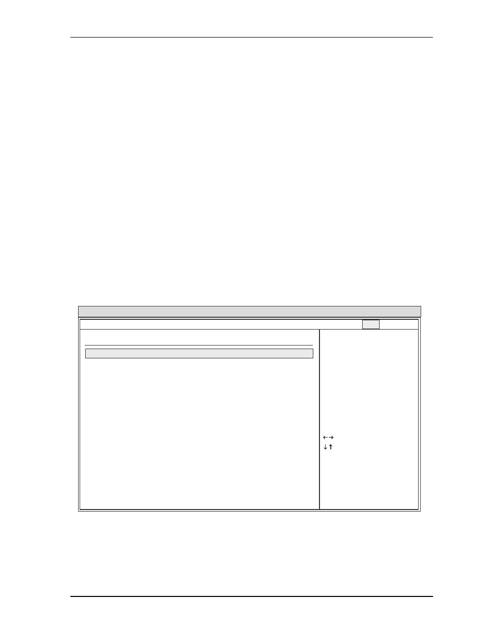
BIOS Exit Setup Screen
Figure 4-7. BIOS Exit Setup Screen
BIOS Setup Utility
Exit Options
Select Screen
Select Item
Enter Go to Sub Screen
F1 General Help
F10 Save and Exit
ESC Exit
x02.xx (C) Copyright 1985-20xx, American Megatrends, Inc.
Save Changes and Exit
Discard Changes and Exit
Discard Changes
Load Optimal Defaults
Load Failsafe Defaults
Main Advanced PCIPnP Boot Security Chipset Exit
CM430_BIOS_ExitScreen_a