Bios pcipnp setup screen, Figure 4-3 – ADLINK CoreModule 430 User Manual
Page 44
Chapter 4
BIOS Setup
38
Reference Manual
CoreModule 430
•
Legacy USB Support – [Disabled; Enabled; Auto]
Note: If Disabled is selected, the following item disappears from the screen.
•
USB 2.0 Controller Mode – [Full Speed; Hi Speed]
•
BIOS EHCI Hand-Off – [Disabled; Enabled]
SB LAN [Enabled; Disabled]
MAC Address XX XX XX XX XX XX
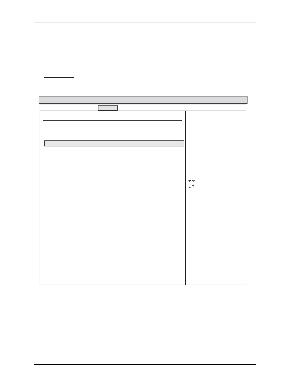
BIOS PCIPnP Setup Screen
Figure 4-3. BIOS PCIPnP Setup Screen
•
Clear NVRAM – [No; Yes]
•
Plug & Play O/S – [No; Yes]
•
PCI Latency timer – [32; 64; 96; 128; 160; 192; 224; 248]
•
Allocate IRQ to PCI VGA – [Yes; No]
•
Palette Snooping – [Disabled; Enabled]
BIOS Setup Utility
Advance PCI/PnP Settings
IRQ3 [Reserved]
IRQ4 [Reserved]
IRQ5 [Available]
IRQ6 [Available]
IRQ7 [Reserved]
IRQ9 [Available]
IRQ10 [Available]
IRQ11 [Available]
IRQ12 [Available]
IRQ14 [Available]
IRQ15 [Reserved]
DMA Channel 0 [Available]
DMA Channel 1 [Available]
DMA Channel 3 [Available]
DMA Channel 5 [Available]
DMA Channel 6 [Available]
DMA Channel 7 [Available]
Reserved Memory Size [Disabled]
Select Screen
Select Item
+ - Change Option
F1 General Help
F10 Save and Exit
ESC Exit
v02.XX (C) Copyright 1985-20XX, American Megatrends, Inc.
WARNING: Setting wrong values in below sections
may cause system to malfunction.
Clear NVRAM
Plug & Play O/S
PCI Latency Timer
Allocate IRQ to PCI VGA
Pallette Snooping
PCI IDE BusMaster
[Enabled]
OffBoard PCI/ISA IDE Card [Auto]
[No]
[No]
[64]
[No]
[Disabled]
Main Advanced PCIPnP Boot Security Chipset Exit
CM430_BIOS_PCIPnPScreen_a