Jumper header definitions, Figure 2-5, Header locations (top side) – ADLINK CoreModule 430 User Manual
Page 17: Table 2-3, Jumper settings
Chapter 2
Product Overview
CoreModule 430
Reference Manual
11
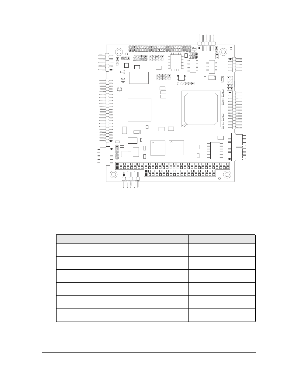
Figure 2-5. Header Locations (Top Side)
Jumper Header Definitions
describes the jumper headers shown in
Note: All jumper headers use 0.079" (2mm) pitch.
Table 2-3. Jumper Settings
Jumper #
Installed
Removed/Installed
JP1 – Serial Port 2
Termination
Enable RS-485 Termination (Pins 1-2)
Disable RS-485 Termination
(Removed) Default setting
JP2 – Serial Port 1
Termination
Enable RS-485 Termination (Pins 1-2)
Disable RS-485 Termination
(Removed) Default setting
JP5 – Backlight
Voltage Select
+5 Volts (Pins 1-2)
+12 Volts (Pins 2-3) Default
JP6 – Flat Panel
Voltage Select
+3.3 Volts (Pins 1-2) Default
+5 Volts (Pins 2-3)
JP7 – Compact Flash
Voltage Select
+5 Volts (Pins 1-2)
+3.3 Volts (Pins 2-3) Default
JP8 – IDE Select
Enable HDD master, CF slave (Pins 1-2)
Default
Enable HDD slave, CF master
(Pins 2-3)
CM430_conn_top_c
J6
J17
J13
J14
J9
J11
J10
P1
J7
J2
J4
J8
J19
J20
J3
J5
JP2
AB
DC
JP1
JP8
JP5
JP6
JP7
Key:
J2 - Fast Ethernet
J3 - COM1
J4 - Parallel
J5 - Utility
J6 - IDE
J7 - Power
J8 - GPIO
J9 - COM2
J10 - USB0
J11 - TTL and VGA Video
J13 - COM4
J14 - COM3
J17 - USB1
J19 - SPI 16 Mbit Data Storage
JP1 - See jumper table
JP2 - See jumper table
JP5 - See jumper table
JP6 - See jumper table
JP7 - See jumper table
JP8 - See jumper table
P1 - PC/104