10 lpt interface (x19), Lpt header (x19) – ADLINK CM1-86DX2 User Manual
Page 42
36
Module Description
3.10 LPT Interface (X19)
The parallel port is located on an IC26 header. An adapter cable with standard DSUB-25 female
connector is available. The parallel port is programmable in BIOS. Enter ADVANCED>CHIP-
SET>Southbridge Configuration>Serial/Parallel Port Configuration for access to the following
settings.
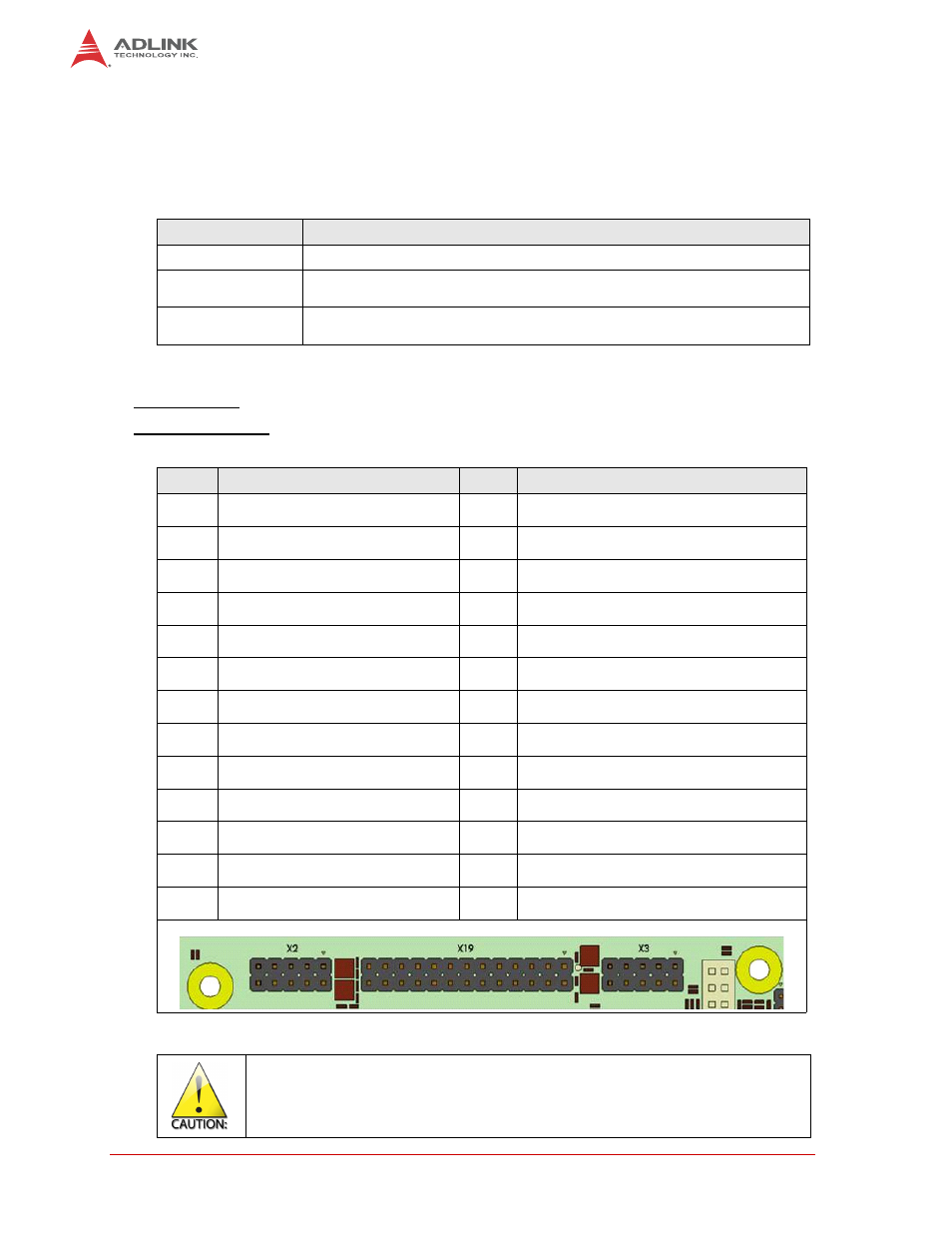
LPT Header (X19)
Connector type: IDC26 pin header, 2.54 mm (X19)
Matching connector: IDC26 pin female connector, 2.54 mm
Table 3-19: BMC Service Connector (X24)
LPT Parameter
Possible Settings
Base Address
Disabled, 0x378 and 0x278
Mode
BPP, EPP 1.9 and SPP, ECP, ECP and EPP 1.9, SPP, EPP 1.7 and SPP, ECP
and EPP 1.7
IRQ
Disabled, IRQ 3, IRQ 4, IRQ 5, IRQ 6, IRQ 7, IRQ 9, IRQ 10, IRQ 11, IRQ 12,
IRQ 14 and IRQ15
Table 3-20: LPT Header Signals (X19)
Pin
Signal
Pin
Signal
1
Strobe
2
Auto LF
3
Data0
4
Error
5
Data1
6
Init
7
Data2
8
Select In
9
Data3
10
GND
11
Data4
12
GND
13
Data5
14
GND
15
Data6
16
GND
17
Data7
18
GND
19
ACK
20
GND
21
busy
22
GND
23
Paper End
24
GND
25
Select
26
+5.0 Volt
The maximum current on all supply pins is 0.5A.