2 getting started, Header and jumper locations, 2getting started – ADLINK CM1-86DX2 User Manual
Page 15: 1 header and jumper locations
Getting Started
9
CM1-86DX2
2
Getting Started
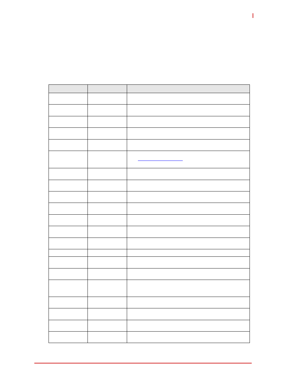
2.1 Header and Jumper Locations
Table 2-1 on page 9 provides descriptions of the headers and connectors on the module. The
header and connector locations are shown in Figure 2-1 and Figure 2-2. See Chapter 3 for the
signal definitions of the headers and connectors presented in this table.
Table 2-1: Connector Name and Description
Connector
Top/Bottom
Description
X1
Top
10-pin, 2.54mm utility header
(AMTEK, PH1M25-205GBCOR600-U)
X2, X3, X4, X5
Top
10-pin, 2.54mm COM headers
(AMTEK, PH1M25-205GBCOR600-U)
X6
Top
10-pin, 2.54mm Gigabit Ethernet header
(AMTEK, PH1M25-205GBCOR600-U)
X7
Top
10-pin, 2.54mm Fast Ethernet header
(AMTEK, PH1M25-205GBCOR600-U)
X8
Top
10-pin, 2.54mm VGA header
(AMTEK, PH1M25-205GBCOR600-U)
X9
Top
104-pin, standard PC/104 connector;
see
http://www.pc104.org
for signal definitions
(EPT, 962-60322-12)
X10
Bottom
52-pin standard, PCIe MiniCard connector
(Attend Technology, 119A-92A00-R02)
X11
Bottom
7-pin standard, right-angle SATA connector
(MOLEX, 47080-4001)
X12
Bottom
30-pin, 1.25mm right-angle, single-row LVDS header
(HIROSE, DF14-30P-1.25H)
X13
Bottom
8-pin, 1.25mm right-angle, single-row backlight header
(HIROSE, DF13-8P-1.25H)
X14
Bottom
8-pin, 1.25mm right-angle, single-row USB header [ports 0-1]
(HIROSE, DF13-8P-1.25H)
X15
Bottom
10-pin, 1.25mm right-angle, single-row miscellaneous header
(HIROSE, DF13-10P-1.25H)
X17
Bottom
10-pin, 1.25mm right-angle, single-row GPIO header
(HIROSE, DF13-10P-1.25H)
X18
Bottom
8-pin standard, right-angle SD Card connector
X19
Top
26-pin, 2.54mm LPT parallel port header
(AMTEK, PH1M25-205GBCOR600-U)
X20
Bottom
6-pin, 2mm mode select jumper header
(W+P Products, 7351-06-20-20-60-00)
X21
Bottom
12-pin, 1.25mm right-angle, single-row GPIO and Analog-In
header
(HIROSE, DF13-12P-1.25H)
X22
Bottom
6-pin, 2mm mode select jumper header
(W+P Products, 7351-06-20-20-60-00)
X23
Top
16-pin, Audio header
(PFL-2X8-2M54-SMD)
X24
Bottom
10-pin, 1.25mm right-angle, single-row test header (not
intended for users)
X25
Top
15-pin, 2.5mm single-row, PC/104 ATX power connector
(JST, B15B-EH-A/LF)