Power button reset switch speaker – ADLINK CM1-86DX2 User Manual
Page 36
30
Module Description
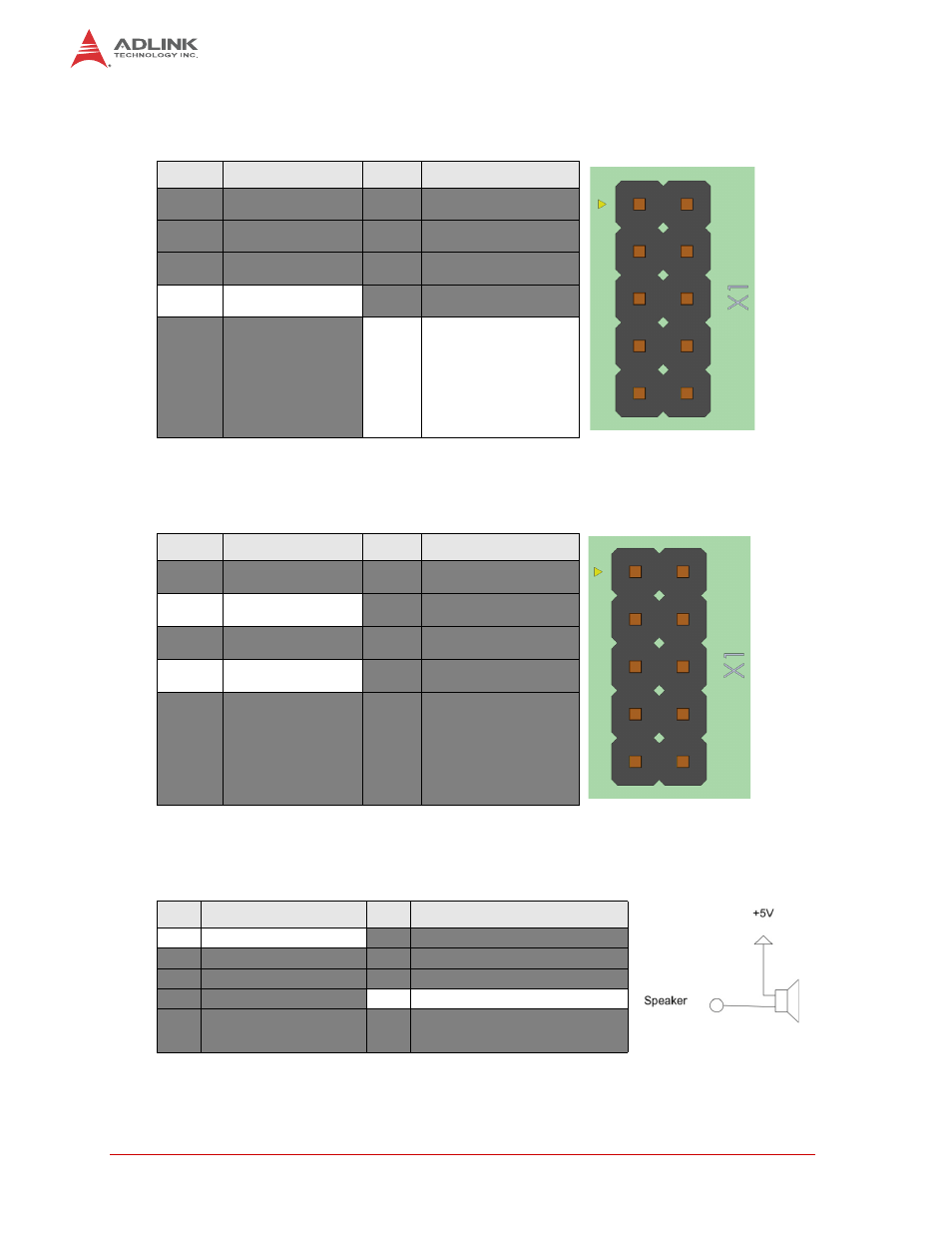
Power Button
To power up/down the board, the signal Power Button must be pulled to GND.
Reset Switch
To reset the CPU using a reset switch, the Reset Switch signal must be pulled to GND.
Speaker
A standard PC Speaker can be connected between the signals Speaker and +5V Standby.
Table 3-12: Power Button Signals (X1)
Pin
Signal
Pin
Signal
1
Speaker
2
Mouse Clock
3
Reset-In
4
Mouse Data
5
KB Data
6
KB Clock
7
GND
8
+5V Standby
9
Ext. Battery
10
Power Button
Table 3-13: Reset Switch Signals (X1)
Pin
Signal
Pin
Signal
1
Speaker
2
Mouse Clock
3
Reset-In
4
Mouse Data
5
KB Data
6
KB Clock
7
GND
8
+5V Standby
9
Ext. Battery
10
Power Button
Table 3-14: Speaker Signals (X1)
Pin
Signal
Pin
Signal
1
Speaker
2
Mouse Clock
3
Reset-In
4
Mouse Data
5
KB Data
6
KB Clock
7
GND
8
+5V Standby
9
Ext. Battery
10
Power Button
- USB-1901 (84 pages)
- USB-1210 (54 pages)
- USB-2401 (60 pages)
- USB-7230 (50 pages)
- USB-2405 (56 pages)
- DAQe-2010 (92 pages)
- DAQe-2204 (100 pages)
- DAQe-2213 (94 pages)
- DAQe-2501 (74 pages)
- PXI-2010 (84 pages)
- PXI-2020 (60 pages)
- PXI-2501 (62 pages)
- cPCI-9116 (98 pages)
- ACL-8112 Series (93 pages)
- ACL-8112 Series (94 pages)
- ACL-8112 Series (92 pages)
- ACL-8216 (75 pages)
- ACL-8111 (61 pages)
- PCM-9112+ (10 pages)
- PCM-9112+ (94 pages)
- cPCI-6216V (47 pages)
- ACL-6126 (28 pages)
- ACL-6128A (40 pages)
- PCM-6308V+ (52 pages)
- PCM-6308V+ (4 pages)
- PCI-7444 (82 pages)
- PCI-7434 (48 pages)
- PCI-7234 (56 pages)
- PCI-7260 (66 pages)
- PCI-7258 (38 pages)
- PCI-7256 (48 pages)
- PCI-7250 (48 pages)
- LPCI-7250 (48 pages)
- PCI-7396 (65 pages)
- PCI-7296 (59 pages)
- PCI-8554 (67 pages)
- PCIe-7360 (94 pages)
- PCIe-7350 (86 pages)
- PCIe-7300A (114 pages)
- PCIe-7200 (51 pages)
- PCI-7300A (112 pages)
- PCI-7300A (83 pages)
- PCI-7200 (96 pages)
- cPCI-7300 (83 pages)
- cPCI-7300 (82 pages)