System fan serial console, Figure 3-1, Hot cable jumper – ADLINK Express-IBR User Manual
Page 42: Table 3-7, Optional system fan (fan1), System fan, Serial console
Chapter 3
Hardware
36
Reference Manual
Express-IBR
System Fan
lists the pin signals of the System Fan interface, which provides a 3-pin, single-row header with
0.049" (1.25mm) pitch.
Note: The shaded table cell denotes power or ground.
Serial Console
The Express-IBR supports the serial console (or console redirection) feature. This I/O function is provided
by an ANSI-compatible serial terminal, or the equivalent terminal emulation software running on another
system. This can be very useful when setting up the BIOS on a production line for systems that are not
connected to a keyboard and display.
Serial Console Setup
The serial console feature is implemented by connecting a standard null modem cable or a modified serial
cable (or “Hot Cable”) between one of the serial ports on the baseboard, such as COM 1, and the serial
terminal or a PC with communications software. The BIOS Setup Utility controls the serial console settings
on the Express-IBR. Refer to
Chapter 4
, BIOS Setup for the settings of the serial console option, the serial
terminal, or PC with communications software, and the connection procedure.
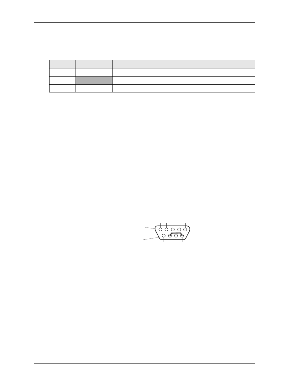
Hot (Serial) Cable
To convert a standard serial cable to a Hot Cable, certain pins must be shorted together at the serial port
(DB9) connector. For example, short together pins 7 (RTS) and 9 (RI) on COM port 1 (DB9) connector as
shown in
.
Figure 3-1. Hot Cable Jumper
Table 3-7. Optional System Fan (FAN1)
Pin #
Signal
Description
1
HWM_PWM2
Modulation – This signal controls the fan speed
2
VCC
+5.0/12.0 volts DC +/- 5%
3
HWM_TACH2
Fan Tachometer – This signal monitors the fan speed
Standard DB9 Serial
Port Connector (Female)
Rear View
5
4
3
2
1
9
8
7
6
Express-IBR_hotcable