Figure 2-5, Connector locations (top side), Figures 2-5 – ADLINK Express-IBR User Manual
Page 18
Chapter 2
Product Overview
12
Reference Manual
Express-IBR
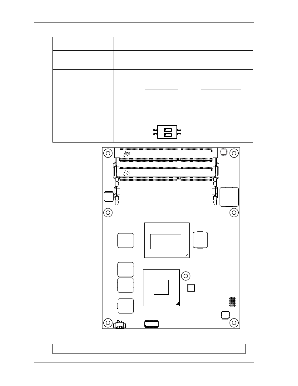
Figure 2-5. Connector Locations (Top Side)
CN7 – COM Express C-D
(see
.)
Bottom
220-pin standard connector for Northbridge Video and
Southbridge I/O functions
FAN1 – System Fan
Top
3-pin, 0.049" (1.25mm) right-angle shrouded header
controlled by the Hardware Monitor for CPU and PCH
cooling
SW1 – PCIe x16 Lane
Configuration Switch (see
.)
Bottom
4-pin dip switch for selecting CPU PCIe x16 lane
configurations
Switch Positions Lane Configurations
Pin 1, Pin 2 (off, off) = 1x8, 2x4
Pin 1, Pin 3 (off, on) = Reserved
Pin 4, Pin 2 (on, off) = 2x8
Pin 4, Pin 3 (on, on) = 1x16 [Default]
NOTE
Pin 1 is shown as a black square on connectors in all illustrations.
Table 2-3. Module Connector and Socket Descriptions (Continued)
Pin 1
Pin 2
Pin 4
ON
1 2
Pin 3
SW1 Configuration Switch
J6
J5
CN4
FAN1
Key:
J5 - Channel A SODIMM socket
J6 - Channel B SODIMM socket
FAN1 - CPU Fan
CN4 - LPC
Express-IBR_T
op_Conn_a