System management bus (smbus) gpio, Table 3-4, Smbus reserved addresses – ADLINK Express-IBR User Manual
Page 34: Table 3-5
Chapter 3
Hardware
28
Reference Manual
Express-IBR
System Management Bus (SMBus)
The I/O Hub (PCH) contains an integrated SMBus controller with both a host and slave SMBus port; but the
host cannot access the slave internally. The slave port allows an external master access to the PCH through
the COM Express A-B connector.
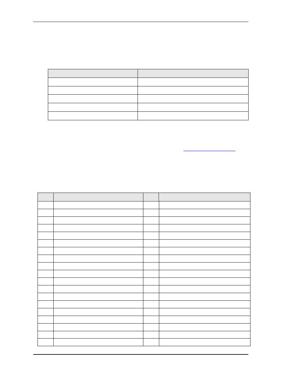
lists the device names and corresponding reserved addresses on
the SMBus.
GPIO
The Express-IBR provides GPIO (General Purpose I/O) pins for custom use through the COM Express A-B
connector. Use the ADLINK Intelligent Device Interface (AIDI) Library to configure the GPIO interface.
AIDI driver information is available on the Express-IBR Product page at:
http://www.adlinktech.com
. An
AIDI demo program and the AIDI User’s Manual describing how to use the GPIO pins also reside in the
Utilities tab of the Express-IBR Product page.
For more information about GPIO pin operation, refer to the PCA9535BS GPIO Generator datasheet. See
for a hyper link to the datasheet.
provides the pin signals for the COM Express A-B connector (CN6).
Table 3-4. SMBus Reserved Addresses
Component
Address (binary)
SODIMM A
1010,000x
b
(A0h hex)
SODIMM B
1010,010x
b
(A4h hex)
Hardware Temp and Voltage Monitor
1011,100x
b
(2Eh hex)
GPIO Generator
1000,000x
b
(40h hex)
Clock Generator
1101,001x
b
(D2h hex)
Table 3-5. COM Express A-B Connector Signal Descriptions (CN6)
Pin #
Row A
Pin #
Row B
A1
GND
B1
GND
A2
GBE0_MDI3-
B2
GBE0_ACT# (PU 330E 3.3V)
A3
GBE0_MDI3+
B3
LPC_FRAME#
A4
GBE0_LINK100# (Ethernet Speed LED)
B4
LPC_AD0
A5
GBE0_LINK1000# (Ethernet Speed LED)
B5
LPC_AD1
A6
GBE0_MDI2-
B6
LPC_AD2
A7
GBE0_MDI2+
B7
LPC_AD3
A8
GBE0_LINK#
B8
LPC_DRQ0# (Int. PU 20k in PCH)
A9
GBE0_MDI1-
B9
LPC_DRQ1# (Int. PU 20k in PCH)
A10
GBE0_MDI1+
B10
LPC_CLK
A11
GND
B11
GND
A12
GBE0_MDI0-
B12
PWRBTN# (PU 10k 3.3VStandby)
A13
GBE0_MDI0+
B13
SMB_CK (PU 8.2k 3.3V Standby)
A14
GBE0_CTREF
B14
SMB_DAT (PU 8.2k 3.3V Standby)
A15
SUS_S3#
B15
SMB_ALERT# (PU 10k 3.3V Standby)
A16
SATA0_TX+
B16
SATA1_TX+
A17
SATA0_TX-
B17
SATA1_TX-
A18
SUS_S4#
B18
SUS_STAT#
A19
SATA0_RX+
B19
SATA1_RX+