11 position compare output cmp, 12 emergency stop input emg – ADLINK HSL-4XMO User Manual
Page 37
Signal Connections
27
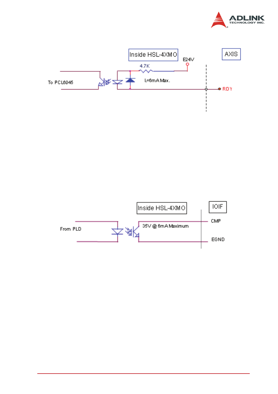
Figure 3-13: General-purpose Signal RDY
3.11 Position Compare Output CMP
The HSL-4XMO provides 4 comparison output channels. The
comparison output channel will generate a pulse signal when the
encoder counter reaches a pre-set value set by the user.
The following wiring diagram is of the CMP signals:
Figure 3-14: Position Compare Output CMP
Note:
CMP trigger type can be set as normal low (rising edge) or
normal high (falling edge). Default setting is normal high.
3.12 Emergency Stop Input EMG
There is emergency stop input pin for this module. When EMG is
active, all the motion pulse output command will be rejected until
the EMG is deactive.
A circuit diagram is shown in the diagram below. The emergency
stop switch should have a contact capacity of +24V @ 6mA mini-
mum. Either ‘A-type’ (normal open) contact or ‘B-type’ (normal
- USB-1901 (84 pages)
- USB-1210 (54 pages)
- USB-2401 (60 pages)
- USB-7230 (50 pages)
- USB-2405 (56 pages)
- DAQe-2010 (92 pages)
- DAQe-2204 (100 pages)
- DAQe-2213 (94 pages)
- DAQe-2501 (74 pages)
- PXI-2010 (84 pages)
- PXI-2020 (60 pages)
- PXI-2501 (62 pages)
- cPCI-9116 (98 pages)
- ACL-8112 Series (93 pages)
- ACL-8112 Series (94 pages)
- ACL-8112 Series (92 pages)
- ACL-8216 (75 pages)
- ACL-8111 (61 pages)
- PCM-9112+ (10 pages)
- PCM-9112+ (94 pages)
- cPCI-6216V (47 pages)
- ACL-6126 (28 pages)
- ACL-6128A (40 pages)
- PCM-6308V+ (52 pages)
- PCM-6308V+ (4 pages)
- PCI-7444 (82 pages)
- PCI-7434 (48 pages)
- PCI-7234 (56 pages)
- PCI-7260 (66 pages)
- PCI-7258 (38 pages)
- PCI-7256 (48 pages)
- PCI-7250 (48 pages)
- LPCI-7250 (48 pages)
- PCI-7396 (65 pages)
- PCI-7296 (59 pages)
- PCI-8554 (67 pages)
- PCIe-7360 (94 pages)
- PCIe-7350 (86 pages)
- PCIe-7300A (114 pages)
- PCIe-7200 (51 pages)
- PCI-7300A (112 pages)
- PCI-7300A (83 pages)
- PCI-7200 (96 pages)
- cPCI-7300 (82 pages)
- cPCI-7300 (83 pages)