9 cm1-cm4 pin assignments: for hsl-4xmo-cd- n/p, Cm1-cm4 pin assignments: for hsl-4xmo-cd-n/p, Connector – ADLINK HSL-4XMO User Manual
Page 23: Nal connector
Installation
13
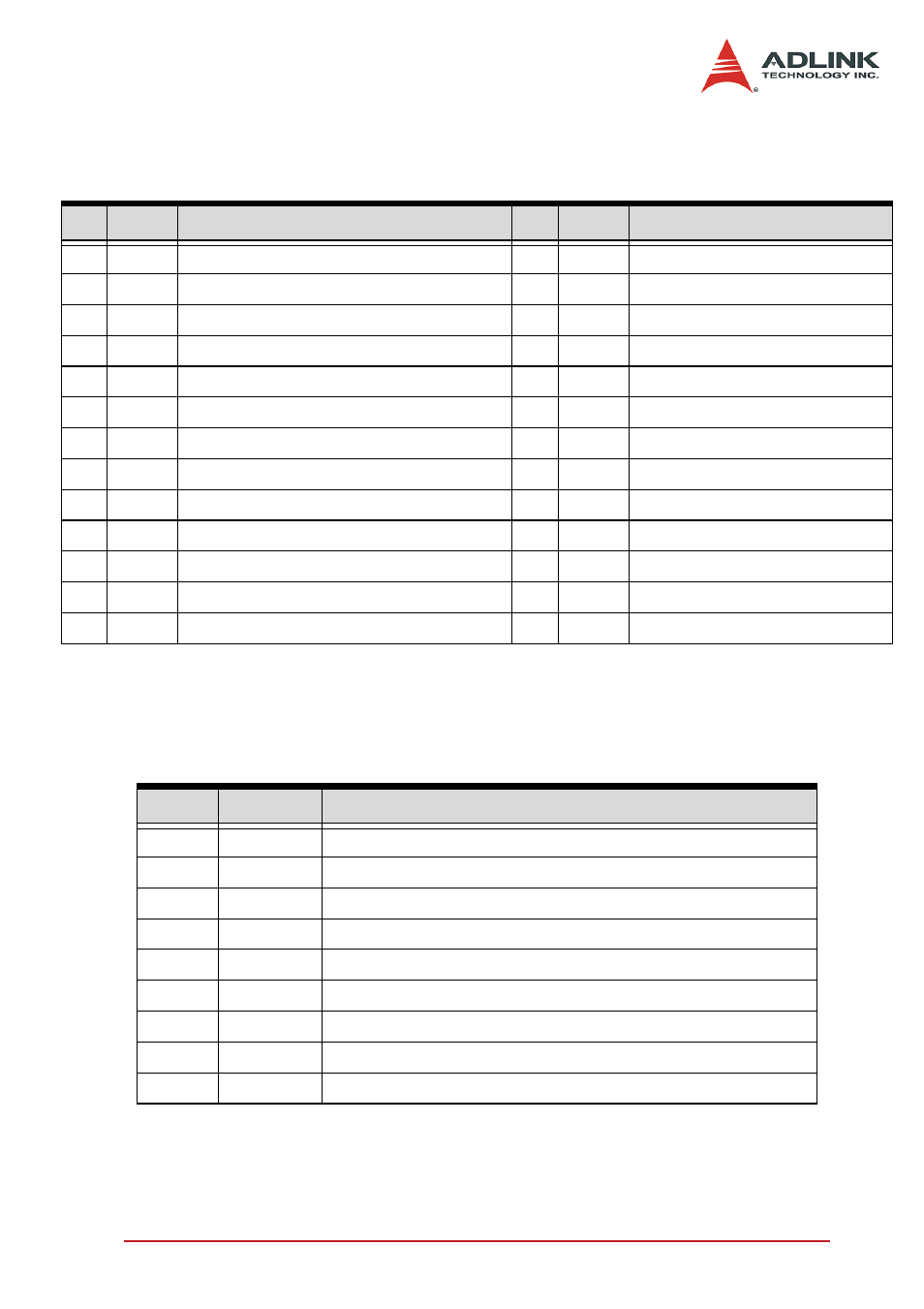
2.9 CM1-CM4 Pin Assignments: For HSL-4XMO-CD-
N/P
2.10
IOIF1-4 Pin Assignments: Mechanical I/O and GPIO Signal Con-
nector
No. Name
Function
No. Name
Function
1
SVON
Servo on output signal
2
INP
In-position input signal
3
ERC Deviation counter clear output signal
4
RDY
Ready input signal
5
OUT-
Pulse signal (-)
6
OUT+
Pulse signal (+)
7
EA-
Encoder A-phase (-)
8
EA+
Encoder A-phase (+)
9
N.C.
Not Connected
10
RST
Alarm reset output signal
11
ALM
Alarm input signal
12
E24V External power supply, +24V
13 EGND
Ext. power ground
14
N.C.
Not Connected
15 PGND
Ground of pulse I/O signals
16
EB-
Encoder B-phase (-)
17
EB+
Encoder B-phase (+)
18 PGND Ground of pulse I/O signals
19
EMG
Emergency stop output signal
20 EGND
External power ground
21 EGND
External power ground
22 EGND
External power ground
23
DIR-
Direction signal (-)
24
DIR+
Direction signal (+)
25
EZ-
Encoder Z-phase (-)
26
EZ+
Direction signal (+)
Table 2-6: CM1-CM4 Pin Assignments: For HSL-4XMO-CD-N/P
Pin No. Pin Name
Description
1
E24V
External power supply, +24V
2
MEL
End limit input signal (-)
3
ORG
Origin input signal
4
PEL
End limit input signal (+)
5
LTC/SD
Ramp-down/position latch input signal (default for LTC)
6
DI/EZ
General purposed input/Index Input
7
DO
General purposed output
8
CMP
Position compare output
9
EGND
External power ground
Table 2-7: IOIF1-4 Pin Assignments: Mechanical I/O and GPIO Signal
Connector