Table 4-7: analog trigger src1 (extatrig) ideal, Transfer characteristic, Figure 4-31: analog trigger block diagram – ADLINK PXI-2208 User Manual
Page 84: Figure 4-31, In figure 4-31)
72
Operation Theory
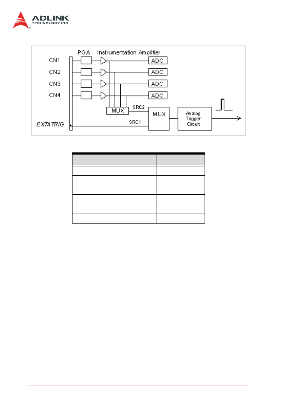
Figure 4-31: Analog Trigger Block Diagram
The trigger signal is generated when the analog trigger condition
is satisfied. There are five analog trigger conditions in the DAQ-/
DAQe-/PXI-2204/2205/2206/2208 card. The DAQ-/DAQe-/PXI-
2204/2205/2206/2208 card uses two threshold voltages,
Low_Threshold and High_Threshold to build the five different trig-
ger conditions. You can configure the trigger conditions easily by
software.
Trigger level digital setting Trigger voltage
0xFF
9.92V
0xFE
9.84V
0x81
0.08V
0x80
0
0x7F
-0.08V
0x01
-9.92V
Table 4-7: Analog Trigger SRC1 (EXTATRIG) Ideal Transfer Characteristic