Table 4-1: bipolar analog input range and output, Digital code on daq/daqe/pxi-2204/2208, Table 4-2: unipolar analog input range and output – ADLINK PXI-2208 User Manual
Page 47
Operation Theory
35
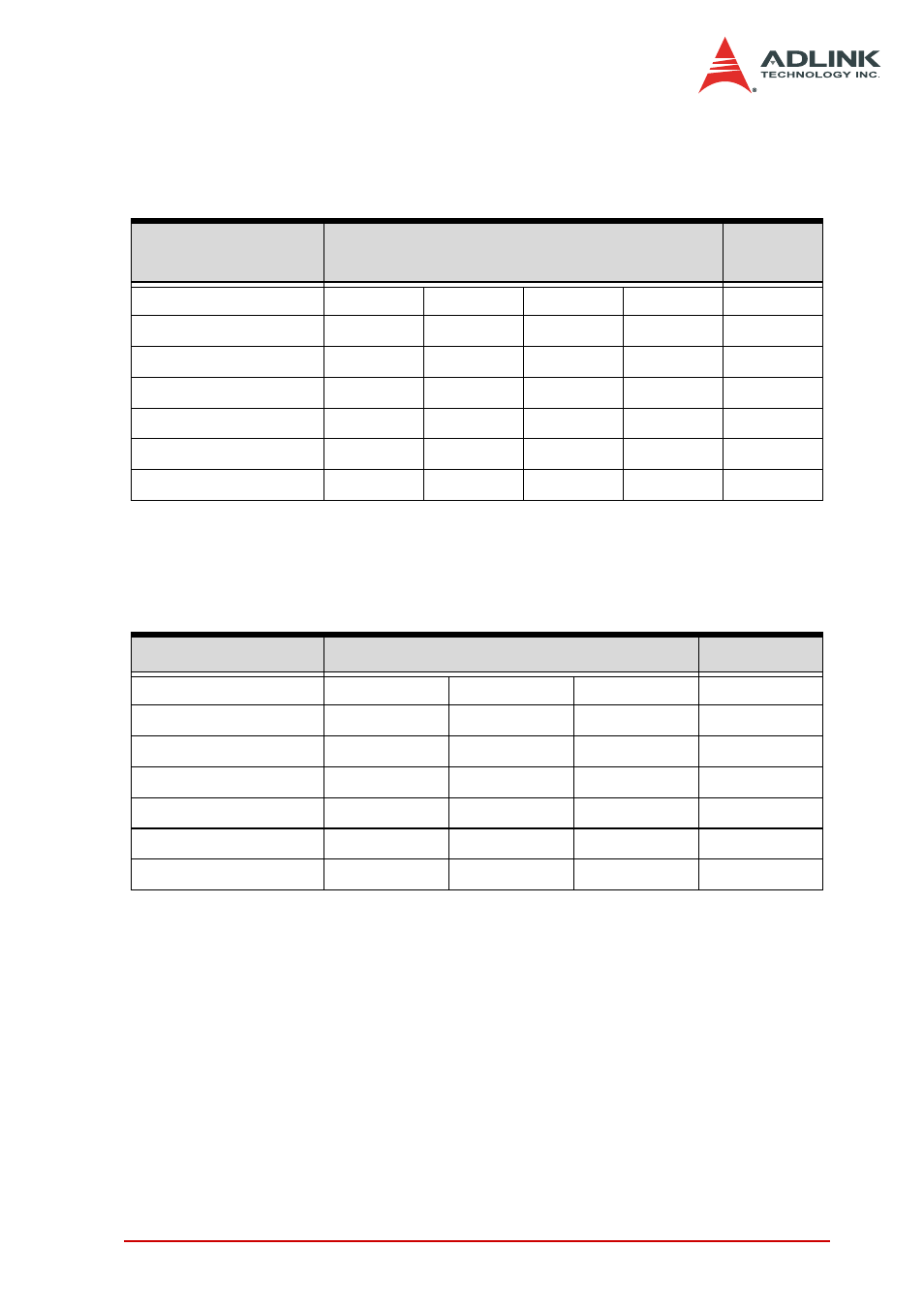
Table 4-1and Table 4-2 illustrate the ideal transfer characteristics
of various input ranges of the DAQ-/DAQe-/PXI-2204/2205/2206/
2208 card.
Note that the last 4 digital codes are SDI<3..0> and is supported only on DAQ-/DAQe-/PXI-
2204)
Note that the last 4 digital codes are SDI<3..0> and is supported only on DAQ-/DAQe-/PXI-
2204.
Description
Bipolar Analog Input Range
Digital
code
Full-scale Range
±10V
±5V
±2.5V
±1.25V
—
Least significant bit
4.88mV
2.44mV
1.22mV
0.61mV
—
FSR-1LSB
9.9951V
4.9976V
2.4988V
1.2494V
7FFX
Midscale +1LSB
4.88mV
2.44mV
1.22mV
0.61mV
001X
Midscale
0V
0V
0V
0V
000X
Midscale –1LSB
-4.88mV
-2.44mV
-1.22mV
-0.61mV
FFFX
-FSR
-10V
-5V
-2.5V
-1.25V
800X
Table 4-1: Bipolar Analog Input Range and Output Digital Code on DAQ/
DAQe/PXI-2204/2208
Description
Unipolar Analog Input Range
Digital code
Full-scale Range
0V to 10V
0 to +5V
0 to +2.5V
—
Least significant bit
2.44mV
1.22mV
0.61mV
—
FSR-1LSB
9.9976V
4.9988V
2.9994V
7FFX
Midscale +1LSB
5.00244V
2.50122V
1.25061V
001X
Midscale 5V
2.5V
1.25V
000X
Midscale –1LSB
4.9976V
2.4988V
1.2494V
FFFX
-FSR
0V
0V
0V
800X
Table 4-2: Unipolar Analog Input Range and Output Digital Code on DAQ/
DAQe/PXI-2204/2208