ADLINK PXI-2208 User Manual
Page 69
Operation Theory
57
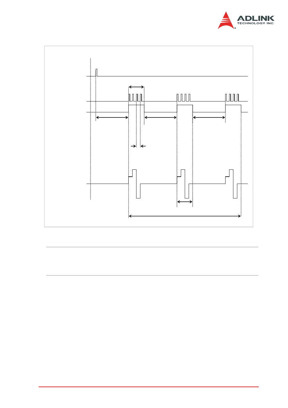
Figure 4-14: Typical D/A Timing of Waveform Generation
NOTE
The maximum D/A update rate is 1 MHz. Therefore, the
minimum setting of the UI_counter is 40 while using an in-
ternal TIMEBASE (40 MHz).
(UC _Counter=4, IC_Counter=3)
4 update counts, 3 iterations
DAWR
WFG_in_progress
DA update_interval t=
UI_Counter/Timebase
Operation start
Trigger
Delay until
DLY1_Counter
reaches 0
Delay until
DLY2_Counter
reaches 0
Output Waveform
Delay until
DLY2_Counter
reaches 0
0
2
4
-4
A single waveform
UC_Counter=4
IC_Counter = 3