Figure 4-3: scan timing – ADLINK PXI-2208 User Manual
Page 51
Operation Theory
39
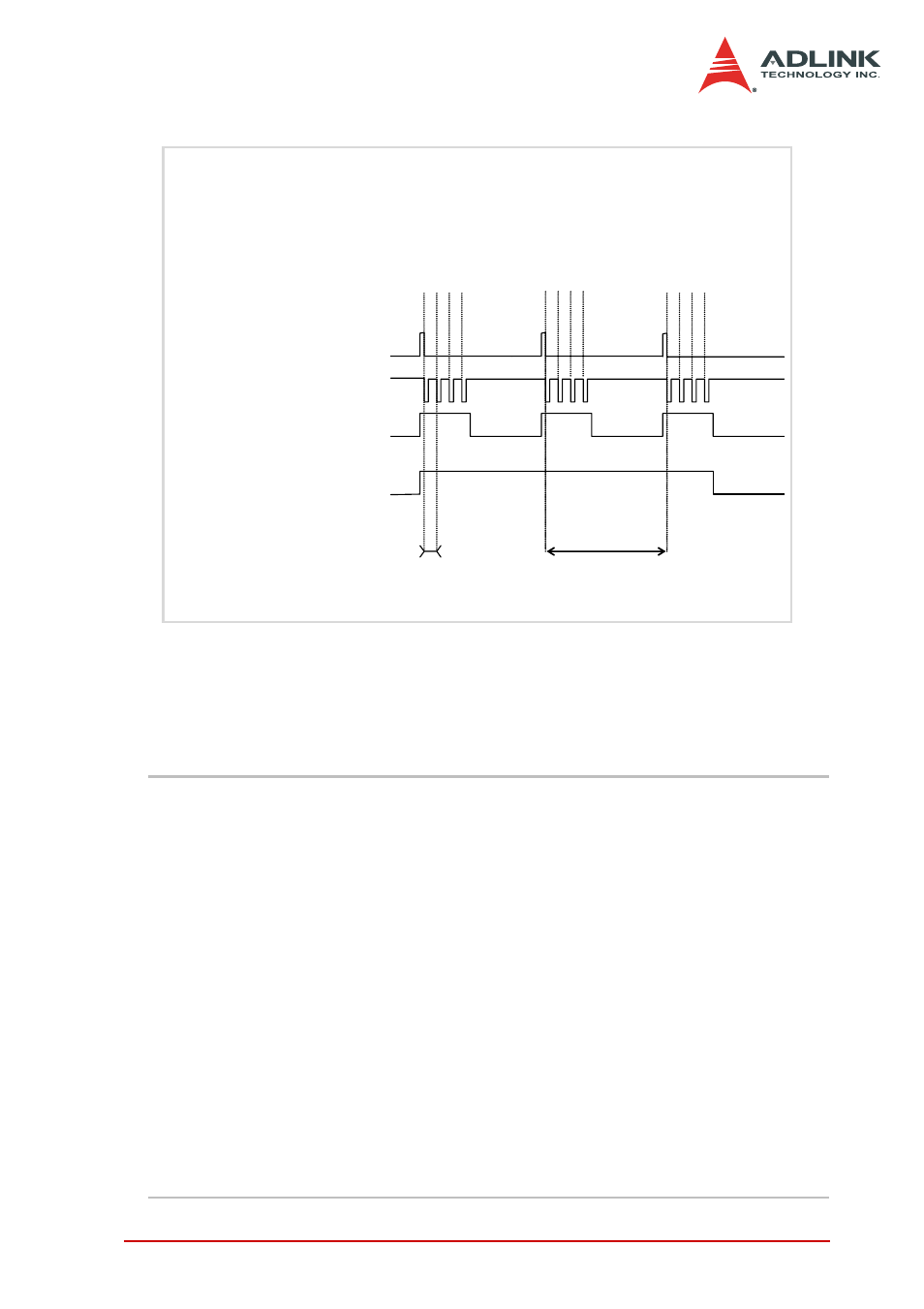
Figure 4-3: Scan Timing
There are four trigger modes to start the scan acquisition. Refer to
section 4.1 for details. The data transfer mode is discussed in the
following section.
NOTES
The maximum A/D sampling rate is 3 MHz for DAQ/
DAQe/PXI-2204/2208, 500 kHz for DAQ/DAQe/PXI-
2205, and 250 kHz for DAQ/DAQe/PXI-2206. Therefore,
the minimum setting of SI2_counter is 14 for DAQ/DAQe/
PXI-2204/2208, 80 for DAQ/DAQe/PXI-2205, and 160 for
DAQ/DAQe/PXI-2206 while using the internal TIME-
BASE.
The SI_counter is a 24-bit counter and the SI2_counter is
a 16-bit counter. The maximum scan interval using the in-
ternal Timebase = 224/40 Ms = 0.419 s, and the maxi-
mum sampling interval between two channels using the
internal Timebase = 216/40 Ms = 1.638 ms.
The scan interval may not be smaller than the product of
the data sampling interval and the NumChan_counter
value. The relationship can be represented as:
SI_counter>=SI2_counter * NumChan_counter.
Acquisition_in_progress
Scan_start
AD_conversion
Scan_in_progress
(SSHOUT)(pin8 on CN2)
3 Scans, 4 Samples per scan
(PSC_Counter=3, NumChan_Counter=4)
Sampling Interval t=
SI2_COUNTER/TimeBase
Scan Interval T=
SI_COUNTER/TimeBase
Ch2
Ch3
Ch1
Ch0
Ch2
Ch3
Ch1
Ch0
Ch2
Ch3
Ch1
Ch0
( channel sequences are specified in Channel Gain Queue)