Carrier 38QB User Manual
Page 9
Attention! The text in this document has been recognized automatically. To view the original document, you can use the "Original mode".
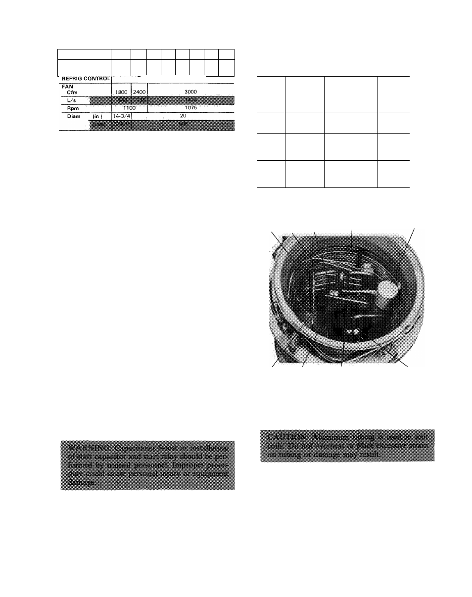
Table 6 — Service Data
Table 7 — Compressor Data (60 Hz)
UNIT 38QB
015
018
024
030
036
042
048; 060
R-22CHG (lb)
40
6 2
7 2
7 3
7 8
8 5
8 6
8 0
AccuRator-'-' (Bypass iypo)
COOLING CYCLE CHARGING CHART
METHOD
1. Operate unit a minimum of 10 minutes be
fore checking charge, and after each charge
adjustment.
2. Measure suction pressure by attaching a gage to
outdoor unit suction service port. (See Fig. 6
for correct service port location on cooling cycle.)
3. Measure outdoor (coil inlet) air dry-bulb tem
perature with service thermometer.
4. Using a sling psychrometer, measure wet-bulb
temperature of air entering indoor unit.
5. Refer to correct Charging Chart. Locate on
curves where outdoor air dry-bulb and indoor
air wet-bulb temperature lines intersect.
6. From intersect point, project vertically down
ward to chart suction pressure line. Compare
chart suction pressure to unit suction pressure
(Step 2).
7. If unit suction pressure is lower than chart pres
sure, add refrigerant to system until chart
pressure is reached. If unit suction pressure is
higher than chart pressure, remove refrigerant
until chart pressure is reached.
Unit Single-Phase Compressors
COMPRESSORS OF THE SPLIT CAPACITOR
(PSC) TYPE require an equalized system pressure
to start. When supply voltage is within nameplate
limit and compressor does not start, give compres
sor a temporary capacitance boost. See Carrier
Standard Service Techniques Manual, Chapter 2,
for details.
Compressor Removal
— See Table 7 for com
pressor information and Fig. 7 for component
location. Shut off power to unit. Remove refrigerant
from unit using refrigerant removal methods de
scribed in Carrier Standard Service Techniques
Manual, Chapter 1, Refrigerants.
Be sure system pressure is 0 psig before
proceeding.
UNIT
38QB
V/PH
PRODUCTION COMPRESSOR
Model*
015
REK3-0125-PFV
20 1
018
CRA1-0150-PFV
51 1
024
208-230/1
MD2314GE
44
i
030
MD3214GE
44 j
036
MD3514GE
44 1
042
PC4616BD
64
048
230/1
PC5016BD
64 1
060
PC6016BD
64 1
036
MF3513GE
44
042
048
208-230/3
PY4616AD
PY5016BD
64
64
060
PY6016BF
64 1
036
MH3513GE
44 i
042
460/3
PH4616AD
64 !
048
PH5016BD
64
060
PH6016BF
64
Oil Recharge
Ounces
‘Refer to Service Parts Catalog for replacement compressor
model numbers
STRAINER VAPOR REVERSING
LINE VALVE
ECOIL
ACCUMULATOR
MUFFLER SOLENOID
HOT GAS
COIL
DISCHARGE LINE
COMPRESSOR
Fig. 7 — Component Location
Follow safety codes. Wear safety glasses and
work gloves. Have quenching cloth available.
1. Remove top cover as described in Installation,
Step 1.
2. Disconnect high- and low-voltage field wiring
and fan motor leads from capacitor and
contactor.
3. Remove screws holding discharge grille in place.
Lift grille from unit.
4. Disconnect compressor leads (crankcase heater,
low-pressure switch, defrost thermostat and
solenoid coil) from electrical components and
pull them thru the wire access opening into the