M 10, Hh0iat171) — set anticipator for room, Table 4 — electrical data (60 hz) – Carrier 38QB User Manual
Page 6
Attention! The text in this document has been recognized automatically. To view the original document, you can use the "Original mode".
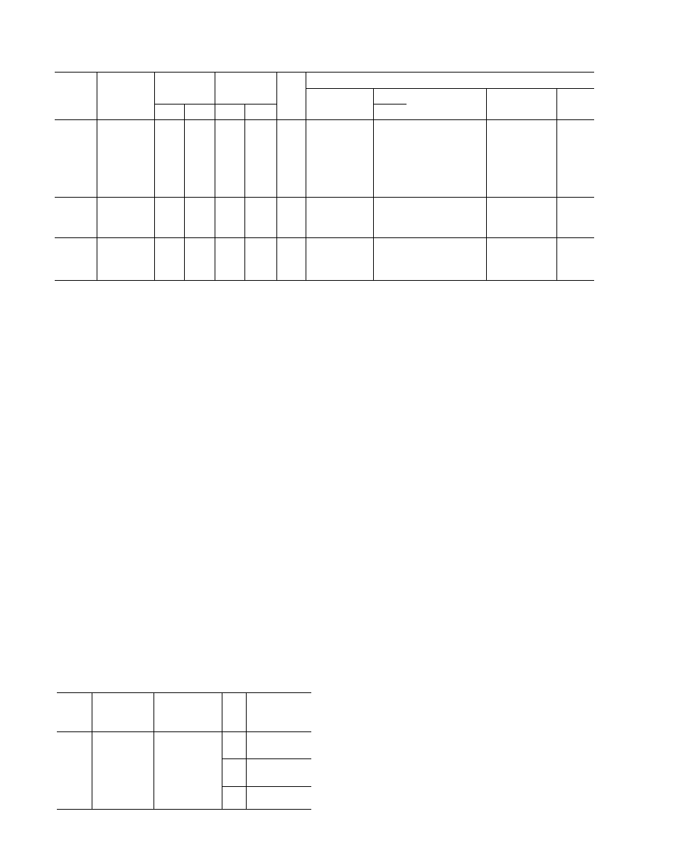
Table 4 — Electrical Data (60 Hz)
UNIT
38QB
V/PH
OPER
VOLTAGE*
COMPR
FAN
FLA
BRANCH CIRCUIT
Min Wire
Size (AWG)t
Max \
'Vire ; 1 Min Gnd
Wire Sizel
Max Fuse**
or HACR Type
Ckt Bkr Amps
MCA
Max
Min
LRA
RLA
015
208-230/1
254
197
34
7 7
1 25
14
40 1
14
15
109
018
208-230/1
254
197
48
124
1 25
14
27 1
u
25
168
024
208-230/1
254
197
66
15 5
24
12
32 ;l
12
35
21 8
030
208-230/1
254
197
82
165
24
12
32 1
12
35
23 0
036
208-230/1
254
197
88
20 6
24
10
39 1
10
45
28 2
042
230/1
254
207
98
199
24
10
44 1
10
45
27 3
048
230/1
254
207
105
22 4
24
8
62 1
10
50
30 4
060
230/1
254
207
130
27 8
24
8
51 I
60
37 2
036
208-230/3
254
197
87
11 7
24
14
32 1
14
25
170
042
208-230/3
254
197
80
13 3
24
14
29 1
14
30
190
048
208-230/3
254
197
80
16 3
24
12
24 1
12
35
22 8
060
208-230/3
254
197
98
20 9
24
10
M 10
45
28 5
036
460/3
506
414
30
5 1
1 2
14
159 1
14
15
76
042
460/3
506
414
35
72
1 2
14
120 1
14
15
102
048
460/3
506
414
40
80
1 2
14
109 1
14
15
11 2
060
460/3
506
414
49
104
1 2
14
_3I
■__________ ______
20
142
AWG — American Wire Gage
FLA — Full Load Amps
FIACR — Heating, Air Conditioning and Refrigeration
LRA — Locked Rotor Amps
MCA — Minimum Circuit Amps
RLA — Rated Load Amps
‘Permissible limits of the voltage range at which the unit will
operate satisfactorily
tCopper wire sizes based on 60C Use copper wire only.
tRequired when using nonmetallic conduit
“Time-delay fuse
NOTE: All units have 24-v control circuit which requires external
power source
CONNECT CONTROL POWER WIRING (24 V)
— Extend wiring thru hole provided (Fig. I) and
into low-voltage section of unit control ring.
Connect leads to control wiring terminal board as
shown in Fig. 5.
Use indoor unit transformer as 24-v supply for
system. At least a 60-va transformer is recom
mended.
Carrier
approved
indoor
units
are
equipped with a 60-va transformer. See indoor
unit data.
Use Carrier accessory indoor thermostat with
suhbase, Table 3.
START-UP
The 38QB unit is equipped with a crankcase
heater. It is recommended that heater be energized a
minimum of 24 hours before starting unit. To ener
gize heater only, turn the thermostat to OFF posi
tion and close electrical disconnect to heat pump.
Heat Anticipator Settings for Room Thermo
stat
(HH0IAT171) — Set anticipator for room
^ Table 5 — Thermostat Anticipator Settings
UNIT
38QB
FIRST-
STAGE
ANTICIPATOR
SETTING
INDOOR
UNIT WITH
ELECTRIC
HEATER
HTR
KW
SECOND-
STAGE
ANTICIPATOR
SETTINGS
015
018
024
030
036
042
048
060
Fixed
40DQ and
40AQ Fan Coil
with 40AQ Htrs
or 40QB,QH
Fan Coil with
40QB Htrs
50
7 5
100
25
150
20 0
25 0
50
30 0
34 0
75
thermostat according to Table 5. These settings may
be changed slightly to provide a greater degree of
comfort for a particular installation.
Accessory Outdoor Thermostat
provides adjust
able outdoor control of accessory electric heater.
This thermostat makes contact when a drop in out
door temperature occurs. It energizes a stage of elec
tric heat when the outdoor temperature setting is
reached, provided the room thermostat is on the
second stage of heating. One outdoor thermostat is
recommended for each stage of electric heat after the
first stage. Set the outdoor thermostat(s) pro
gressively lower for each stage. Refer to heat load of
building and unit capacity to determine the correct
outdoor thermostat settings.
The accessory supplemental heat relay is required
when 2 outdoor thermostats are used. It is auto
matically energized by the manually operated
supplemental heat switch in the indoor thermo
stat subbase. The thermostat locks out compressor
and the relay bypasses the outdoor thermostats for
electric heater operation during heat pump shut
down. When one outdoor thermostat is used, a sup
plemental heat relay is not required. The supple
mental heat switch in the indoor thermostat subbase
bypasses outdoor thermostat, locks out compressor
and activates electric heater.
MOUNT OUTDOOR THERMOSTAT on control
ring, to the left of the low-voltage control connec
tion. See Fig. 1.
Attach brackets with short sheet metal screws to
avoid contaet with coil. Leave capillary tube coiled
in control compartment making sure it is clear of all
electrical connections and sharp metal edges.