Table 3 — accessories – Carrier 38QB User Manual
Page 4
Attention! The text in this document has been recognized automatically. To view the original document, you can use the "Original mode".
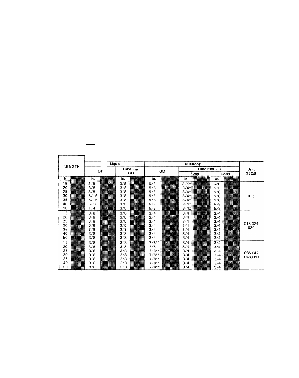
Table 3 — Accessories
PART NO.
DESCRIPTION
UNIT 38QB
99TZ90040106
Low-Voltage Control — Honeywell Thermostat HH07AT171 and
Thermostat Subbase HH93AZ173 — (Automatic Changeover)
99TZ90041106
Low-Voltage Control — Honeywell Thermostat HH07AT171 and
Thermostat Subbase HH93AZ175 — (Manual Changeover)
All
38QB90002106
Service Sentry (Six HN65CT004)
99TZ90029101
Honeywell — Manual Changeover. 2-Stage Heating, 1-Stage Cooling
28AU90006112
Twelve 3/4- x 1-1/8 in. Connection Adapters
042-060
38R090008106
Bi-Flow Heat Pump Filter Drier
(Six
KH45LD077)
HN65DE026*
Supplemental Heat Relay-
(Service Parts)__________
- (Required with 2 Outdoor Thermostats )
38HQ900002
Outdoor Thermostat (Six 38HQ900011)
All
38CQ900172
0ptimizerControlOutdoorThermostat(Six38CO900161 ref HH22AG110)
38RQ900091
Optimizer II Control Assembly (Use with HH2AG1 lOoutdoorthermostat.)
38QB90001106
Heat Pump Rack (Six)
015-018
38QF90000106
Heat Pump Rack (Six)
024-060
38HQ90014106
Optimizer III (Six 38HQ900141)
38QB90003106
Solid-State Time Guard II (24-volt)
All
HC95DD120*
Start Capacitor
015
HC95DD12V
Start Capacitor
018
HC95DD058*
Start Capacitor
024,030
HC95DD088*
Start Capacitor
036
HN61HB515*
Relay
015,018
HN61HB496*
Relay
024,030,036
38EB660002*
TUBING
PACKAGE
38LS958151
38LS958201
38LS958251
38LS958301
38LS958351
38LS958401
38LS958501
38LS934151
38LS934201
38LS934251
38LS934301
38LS934351
38LS934401
38LS934501
38LS978151
38LS978201
38LS978251
38LS978301
38LS978351
38LS978401
38LS978501
Wire Bundle for Start Capacitor and Relay
015-036
TUBING
*Available thru Carrier Service Parts
tSuction line is insulated and has 90° bend
tFor 5/8-in (15 9-mm) evaporator connection, cut off 3/4-in (19 05-mm) belled end
‘‘Capacity reduction may occur when 7/8-in (22 22-mm) accessory tubing is used on 38QB042,048,060
A capacity reduction will result if accessory tub
ing is used in 38QB042 systems. For example, when
a 25-ft (7.6-m) 7/8-in. (22-mm) accessory package is
used, there is a capacity reduction of 1-1/2percent.
When other than 25 ft (7.6 m) of interconnecting
tubing is used, follow special requirements described
in Refrigerant Charging. Do not use less than 10 ft
(3 m) of interconnecting tubing. Do not cut 5/ 16-in.
(7.9-mm) or 1/4-in. (6.4-mm) liquid line due to
swage at ends. Do not cut 7/8-in. (22.22-mm)
suction line. Bend or coil to fit.
Do not use damaged or contaminated tubing.
Always evacuate or purge evaporator coil and
tubing system (use field-supplied refrigerant, not
unit refrigerant).
When making tubing connections, be sure to
provide clearance at unit for electrical connections.