Carrier 38QB User Manual
Page 8
Attention! The text in this document has been recognized automatically. To view the original document, you can use the "Original mode".
MOUNT SUPPLEMENTAL HEAT RELAY in
convenient location on indoor unit. Attach with
sheet metal screw.
To Start Unit
— (Make sure crankcase heater has
been energized for 24 hours.) Adjust the thermostat
as follows:
1. Set selector switch at OFF.
2. Turn on main disconnect switch(es) to indoor
and outdoor units.
3. Set fan switch as desired (ON or AUTO.).
4. Set thermostat dial at desired temperature.
5. Set selector switch at HEAT or COOL.
Check system refrigerant charge. See Refrigerant
Charging.
SERVICE
Refrigerant Charging
— The 38QB units contain
correct operating charge for complete system when
connected to 28HQ,VQ, 40QB,QH or 40AQ indoor
units with 25 ft (7.6 m) of tubing of recommended
diameter. Charge adjustment is required on other
systems. Adjust system charge for refrigerant line
lengths and diameters that differ from 25 ft (7.6 m)
and 3/8in. (10mm) OD (liquid line), respectively,
using refrigerant weights below. Twenty-five ft
(7.5-m), 3/8-in. (lO-mm)ODtubingcontains 14.4 oz
(.4 kg) of R-22. Add R-22 charge to system if liquid
line is over 25 ft (7.6 m); remove charge if liquid
line is shorter than 25 ft (7.6 m).
When recharging is necessary during heating or
cooling season, weigh in total charge indicated in
Table 6. (Charge must be weighed in during heating
season.) Remove any refrigerant remaining in sys
tem before recharging. If system has lost complete
charge, triple-evacuate system to 5000 microns
(29.7 in. [100.5 kPa] vacuum) before recharging.
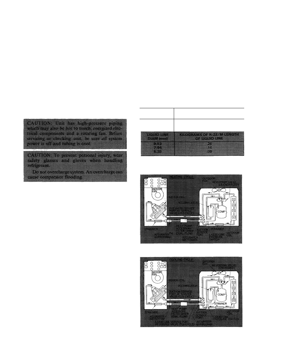
Service port connections are provided on liquid and
suction line service valves for evacuation and charg
ing. (See Fig. 6 for correct service port location
on cooling and heating cycles.) Dial-a-charge
charging cylinder is an accurate device used to re
charge systems by weight. These cylinders are avail
able at refrigeration supply firms.
To check and/or adjust charging during cooling
season, use correct Cooling Cycle Charging Chart
(Fig. 8, 10, 12, 14, 16, 18, 20, 22) and follow
Charging Chart Method below. The charging chart
may also be used as an alternate method of recharg
ing system.
To check system operation during heating cycle,
use correct Heating Cycle Operation Check Chart
(Fig. 9, 11, 13, 15, 17, 19,21,23). These charts indi
cate whether a correct relationship exists between
system operating pressures and air temperatures
entering indoor and outdoor units. If pressure and
temperature lines do not intersect on chart, the sys
tem refrigerant charge may not be correct or other
system abnormalities may exist. Do not use Opera
tion Check Charts to adjust refrigerant charge.
Weigh charge into system.
LIQUID LINE
DIAM (in.)
OUNCES OF R-22/FT LENGTH
OF LIQUID LINE
3/8
.58
5/16
36
1/4
.21
Fig. 6 — 38QB Refrigerant Flow Diagrams