Carrier 38QB User Manual
Page 10
Attention! The text in this document has been recognized automatically. To view the original document, you can use the "Original mode".
coil section. Lift fan orifice/control ring after
pinching and pressing down on 3 plastic pins of
tube supports.
5. Remove louvered casing by taking out 16 screws
seeuring it to the cabinet and sliding it away
from the eoil.
6. Using a midget tubing cutter, cut liquid and
discharge lines on the coil and suction and
discharge lines at a convenient place near the
compressor for easy reassembly with copper
slip couplings.
8
.
7. After plugging connections, remove condenser
coil by pinching plastic pins of tube supports
that extend into basepan and lift vertically.
Set coil on a clean, flat surface.
Remove compressor holddown bolts and slide
out compressor. Remove crankcase heater.
9.
Carefully unbraze suction and discharge line
piping stubs from compressor after noting posi
tion of stubs to assist when reinstalling.
10. Install new eompressor, placing crankcase
heater around compressor. Be sure compressor
holddown bolts are in place.
11. Replace coil; braze suction and discharge lines
to compressor piping stubs (at points where cut.
Step 6); rewire compressor and leak test.
12. Replace fan orifice/control ring; connect com
pressor wires after feeding them thru control
ring; replace fan/grille assembly and rewire;
connect high- and low-voltage power wiring;
and replace louvered casing.
13. Replace top cover by running 4 screws into
orifice loosely (2 on each side of unit) and
tighten when cover is in place. Replace remain
ing screws.
14. Evacuate and recharge system.
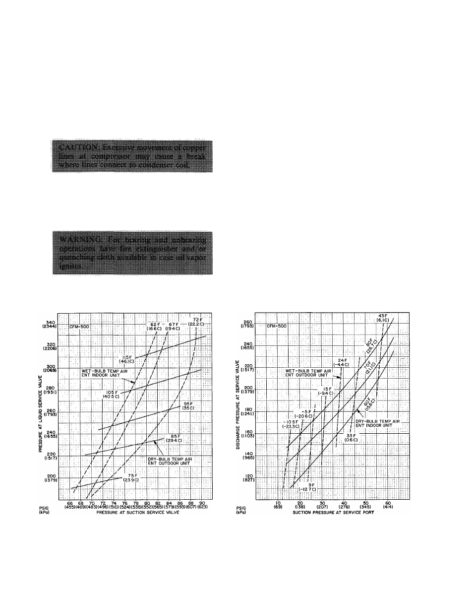
CHARGING AND PRESSURE CHECK CHARTS
Fig. 8 — 38QB015 with 28HQ.VQ018,
40AQ018 or 40DQ018 Cooling Cycle
Charging Chart
Fig. 9 — 38QB015 with 28HQ,VQ018,
40AQ018 or 40DQ018 Heating Cycle
Operation Check Chart
10