Table 1 — carrier approve^^6^ systems, Step 2 — mount outdoor heat pump, Step 3 — make piping connections – Carrier 38QB User Manual
Page 2
Attention! The text in this document has been recognized automatically. To view the original document, you can use the "Original mode".
^ Table 1 — Carrier Approve^^6^ Systems
OUTDOOR
UNIT
38QB
REQUIRED
OUTDOOR
PISTON
SIZE
INDOOR
UNIT
MODEL 8i
SIZE
REQUIRED
INDOOR
PISTON
SIZE
015
38
28HQ.VQ018
40AQ018
46
40DQ018
46*
018
42
28HQ.VQ024
40AQ024
40DQ024
52*
28HQ.VQ024
55
40AQ024
55*
024
46
40DQ024
59
28HQ.VQ030
40AQ030
40DQ030
61*
28HQ.VQ030
63
40AQ030
63*
030
59
40DQ030
63
28HQ.VQ036
40AQ036
40FS160 1 28HQ.VQ036
70*
036
61
28HQ.VQ036
40AQ036
40FS160 1 28HQ.VQ036
67
28HQ.VQ042
40FS160 1 28HQ.VQ042
40QB.QH042
76
042
63
28HQ.VQ042
40FS160 I 28HQ,VQ042
40QB.QH042
76
048
73
28HQ.VQ048
40FS200 1 28HQ.VQ048
40QB.QH048
86*
060
82
40QB.QH060
93
‘Replace factory-installed piston with this piston size
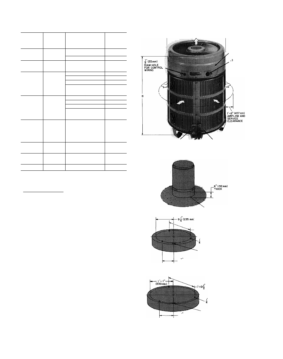
Top Cover Removal — Top cover can be removed
for wiring or servicing heat pump. Loosen decora
tive strip and slide down off screw heads. Remove
3 screws in connector plate and 2 screws on front of
unit. Loosen remaining 4 serews. Lift top from unit
(see Fig. 1).
Step 2 — Mount Outdoor Heat Pump
ON THE GROUND: MOUNT ON A SOLID
LEVEL CONCRETE PAD (see Fig. 1). Swing 3
legs down and lock in position, except when using
accessory rack. Use accessory heat pump rack
(Fig. 2) in areas where prolonged subfreezing tem
peratures or heavy snow occur. (Refer to installation
instructions included with rack.) Drainage holes in
unit base must not be obstructed.
ON THE ROOF; MOUNT ON A LEVEL PLAT
FORM OR FRAME. Proper precaution must be
taken for support of unit in roof design. Elevate unit
for proper clearance as described under ground
installation, above. Plan roof design and water
drainage to prevent unit from setting in water. Flash
all roof openings to prevent leaks.
Roof mounted units exposed to winds above
5 mph (8 km/h) may require protective wind baffles
(field fabricated) to achieve adequate defrost.
Step 3 — Make Piping Connections
— Heat
pumps may be eonneeted to indoor sections using
Carrier aecessory tubing package (Table 3) or field-
supplied tubing of refrigerant grade, correct size and
4'-0" (1220 mm) OVERHEAD SPACE REQUIRED
FOR SERVICE AND AIRFLOW
TOP
COVER
DIAM HOLE
FOR POWER
WIRING
I
LIQUID VALVE SERVICE PORT
f
VAPOR VALVE SERVICE PORT
[//> AIRFLOW
SUCTION SERVICE PORT
12 (305mm)
GRAVEL APRON
I-4 (407mm) TYPICAL 3 PLACES
(6.35 mm) TIEDOWN BOLTS
CENTERLINE BETWEEN
VALVES
6^ (172 mm)
Г-н" (585mm) DIAM x 6"(l52mm)THK CONCRETE
MOUNTING PAD FOR 38QB0I5
(572 mm) TYPICAL 3 PLACES
(6.35 mm) TIEDOWN BOLTS
CENTERLINE BETWEEN
VALVES
9^ (241 mm)
2-6" (762 mm) DIAM x 6" (152mm) THK CONCRETE
MOUNTING PAD FOR 38QB0i8-060
Fig. 1 — Dimensions, Connections and
Mounting Pad (Refer to Table 2.)