Carrier 38QB User Manual
Page 15
Attention! The text in this document has been recognized automatically. To view the original document, you can use the "Original mode".
With a low-side leak there is always some pressure
in the liquid line. However, compressor motor tem
perature increases because of insufficient suction
gas cooling. This causes internal thermostat to
actuate and stop compressor. When compressor
stops, system pressure equalizes and contacts on
pressure control open. The compressor cannot
restart until leak is repaired and system recharged.
CRANKCASE HEATER is connected across line
side of contactor and operates continuously.
The purpose of the heater is to keep the crankcase
warm during the off cycle and thus prevent dilution
of the oil with refrigerant. This assures good lubrica
tion and prevents loss of oil from crankcase during
start-up.
To energize crankcase heater, turn thermostat to
OFF position and energize electrical disconnect to
heat pump.
If the electrical disconnect switch to the outside
unit has been off for an extended period of time, the
crankcase heater should be energized for 24 hours
before starting the compressor.
DEFROST CONTROL, consisting of defrost
control board and defrost thermostat, interrupts
normal system heating operation every 90 minutes
to defrost outdoor coil, if the coil saturated suc
tion temperature indicates freezing temperatures.
Defrost control simultaneously stops outdoor fan,
energizes reversing valve solenoid to return system
to cooling cycle (outdoor unit as condenser, indoor
unit as evaporator), and activates accessory electric
heater.
For the heat pump to defrost, 2 conditions are
necessary:
1. Defrost timer contacts must be closed.
2. Refrigerant temperature from outdoor unit must
be cold enough to cause defrost thermostat
contacts to close. Contacts close at 31 ± 4F
(-.5 + 2.2 C).
Every 90 minutes of elapsed running time, the de
frost timer contacts close for 10 seconds. If the
defrost thermostat contacts are closed, the unit
defrosts. The defrost timer limits defrosting period
to 10 minutes. Normally, the frost is removed and
the defrost thermostat contacts open to terminate
defrosting before 10 minutes have elapsed. Defrost
thermostat contacts open at 80 ± 6 F (26.7 ± 3.3 C)
liquid refrigerant temperature. When defrosting is
terminated, the outdoor fan motor is energized and
reversing valve solenoid is de-energized, returning
unit to heating cycle.
HEAT PUMP CIRCUITS shown in Fig. 6 are re
frigerant flow diagrams for heating and cooling
cycles.
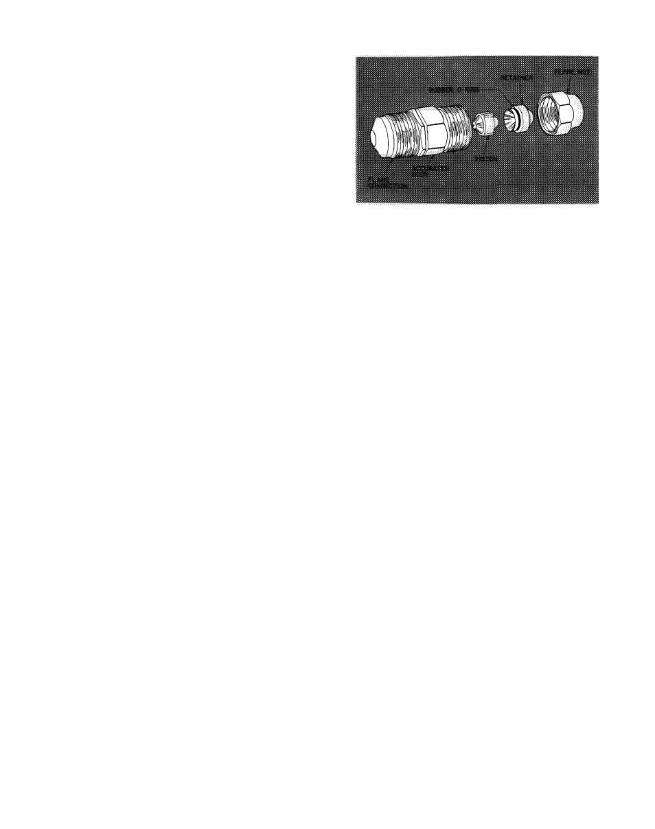
AccuRater™ (Bypass-Type) Servicing
— See
Fig. 24 for bypass-type AccuRater components. The
piston has a refrigerant metering hole thru it. The
retainer forms a stop for the piston in the refrigerant
Fig. 24 — AccuRater (Bypass-Type)
Components
bypass mode, and a sealing surface for liquid line
flare connection. To check, clean or replace piston:
1. Shut off power to unit.
2. Pump unit down using Pumpdown Procedure
described previously.
3.
Remove liquid line flare connection from
AccuRater.
4. Pull retainer out of body, being careful not to
scratch flare sealing surface. If retainer does not
pull out easily, carefully use locking pliers to
remove retainer.
5. Slide piston out by inserting a small soft wire,
with small kinks, thru metering hole. Ensure
metering hole, sealing surface around piston
cones and fluted portion of piston are not
damaged.
6. Clean piston refrigerant metering hole.
7. Replace retainer O-ring before reassembling
bypass-type AccuRater. Carrier O-ring part no.
is 99CC501052.
LIQUID LINE STRAINER (protects AccuRater)
made of wire mesh is located in the liquid line inside
38QB unit behind liquid line service valve. Liquid
line is belled and sweat connected where strainer is
located. If strainer is plugged, unsweat belled liquid
line connection and replace strainer. See Fig. 7.
Compatible Fitting Repair
LEAKING MECHANICAL CONNECTION —
Frontseat outdoor section service valves after reliev
ing refrigerant pressure in system. Back locknut off
Carrier Compatible Fitting onto tube. Cut fitting
between threads and O-ring shown in Fig. 25. Re
move tubing section remaining in threaded portion
of fitting. Discard locknut.
Clean, flux, and insert new tube end into remain
ing portion of Carrier Compatible Fitting. Wrap
valve base in wet rag. Heat and apply low-
temperature solder (430 F [221 C]).
LEAKING SWEAT CONNECTION — Frcntseat
service valves and relieve refrigerant pressure in
tubing. Clean and flux area around leak and apply
low-temperature solder (430 F [221 C]).
15