4it ip, I-ì4, Pumpdown procedure – Carrier 38QB User Manual
Page 14: Unit controls and safety devices, Table 8 — pressure switch settings
Attention! The text in this document has been recognized automatically. To view the original document, you can use the "Original mode".
360
(2482)
340
(2344)
3
300
> (2069)
01
a
S
280
5 (1931)
!;
I 260
« (1793)
240
(1655)
220
(1517)
ÌFH
-r^
. ;TT
: (li
4 ì it
-4 f4-
rii^
P 62 F
pi (I6.6C)
Pi
:|T|C =•1^1=2
000:
til
i-PP-
■ j f!
p| i4
ri ;J
w
P H
liii- iiO
Pi
tp
1 u t
: 1 ! . II5F 4P;
tp.
P
h
ET-
NT IN
i-iiL
3ULB
DOOF
TrPF(46.l(
TEMPAIR
p:[
UT
itlp
;jj E
UNIT
1 P i | P : i
• 1 r i
M i !
4it ip
t-pt
05 F
pii
iPr
T-i ¡J-
'P';
h: :p i-y (4 O.bC ) /
RT
pp-ip-
JP
'Hi-
-Hip
l:.i±r
44-
-i/-
iH-p
Ìpi;
:[n
i|4
1 i -
-7;
-PI
96F
350
"7
ii:i-
P
l
/ i -
1 ,
;
:
! : :
t
TTtt
tr
Pi-
f-r:
f
i_!_;
Fi" ” PI
44
p4
ijtr Ì:I
t
r 85 F
i (29.4 C)
44:
l'r :
44-4 4
pH;
fip
■PP
T
/. :
S
44
ÌÌ4
i-Ì4#
t/ ■
Cil:
j
pi
iP
'-'
t
P : ; 1 .
LI ■ :
iitt
tm
-jfiP
P;
l
2lii ip-
ì
4H-
ì
S
l
ifii
■fljH
ljp
PII
PSIG
(kPa)
64
(441)
68
(469)
72
(496)
76
(524)
80
(552)
PRESSURE AT SUCTION SERVICE VALVE
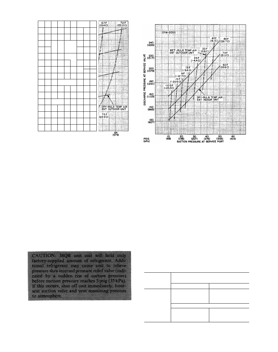
Fig. 22 — 38QB060 with 40QB,QH060
Cooling Cycle Charging Chart
Fig. 23 — 38QB060 with 40QB.QH060
Heating Cycle Operation Check Chart
Filter Drier
— Install field-supplied filter drier
(Table 3) in system liquid line when refrigerant sys
tem is opened for service as described under Com
pressor Removal. Position drier in liquid line at
convenient location.
Pumpdown Procedure
— The system may be
pumped down in order to make repairs on low side
without losing complete refrigerant charge.
1. Attach pressure gage to suction service valve
gage port.
2. Frontseat the liquid line valve.
3. Start unit and run until suction pressure reaches
5 psig (35 kPa) (see Caution).
4. Shut unit off and frontseat suction valve.
5. Vent remaining pressure to atmosphere.
Unit Controls and Safety Devices
HIGH-PRESSURE RELIEF VALVE is located in
compressor. Relief valve opens at a pressure differ
ential of approximately 500 psig (3448 kPa) between
suction (low side) and discharge (high side) to allow
pressure equalization.
INTERNAL CURRENT AND TEMPERATURE
SENSITIVE OVERLOAD resets automatically
when internal compressor motor temperature drops
to a safe level (overloads may require up to 45
minutes to reset). When an internal overload is
suspected of being open, check by using an ohm-
meter or continuity tester. If necessary, refer to
Carrier Standard Service Techniques Manual,
Chapter 2, for complete instructions.
LIQUID
LINE
LOW-PRESSURE
SWITCH
(LLPS) is connected in liquid line to work with
compressor internal thermostat in providing loss-of-
charge protection during the heating cycle. Control
is mounted on liquid line.
With a high-side leak, pressure gradually de
creases until low-pressure control stops the com
pressor. (Low-pressure control settings are shown
in Table 8.)
Table 8 — Pressure Switch Settings
UNIT
38QB
LIQUID LINE
LOW-PRESSURE SWITCH
Cut-in
Cutout
015
018
024
030
2 2 +
5t)sis
7
±
3 psio
036
042
048
060
14