In-line impeller design, Flash and thermal economizer, Thermal purge – Carrier 19 Series User Manual
Page 6
Attention! The text in this document has been recognized automatically. To view the original document, you can use the "Original mode".
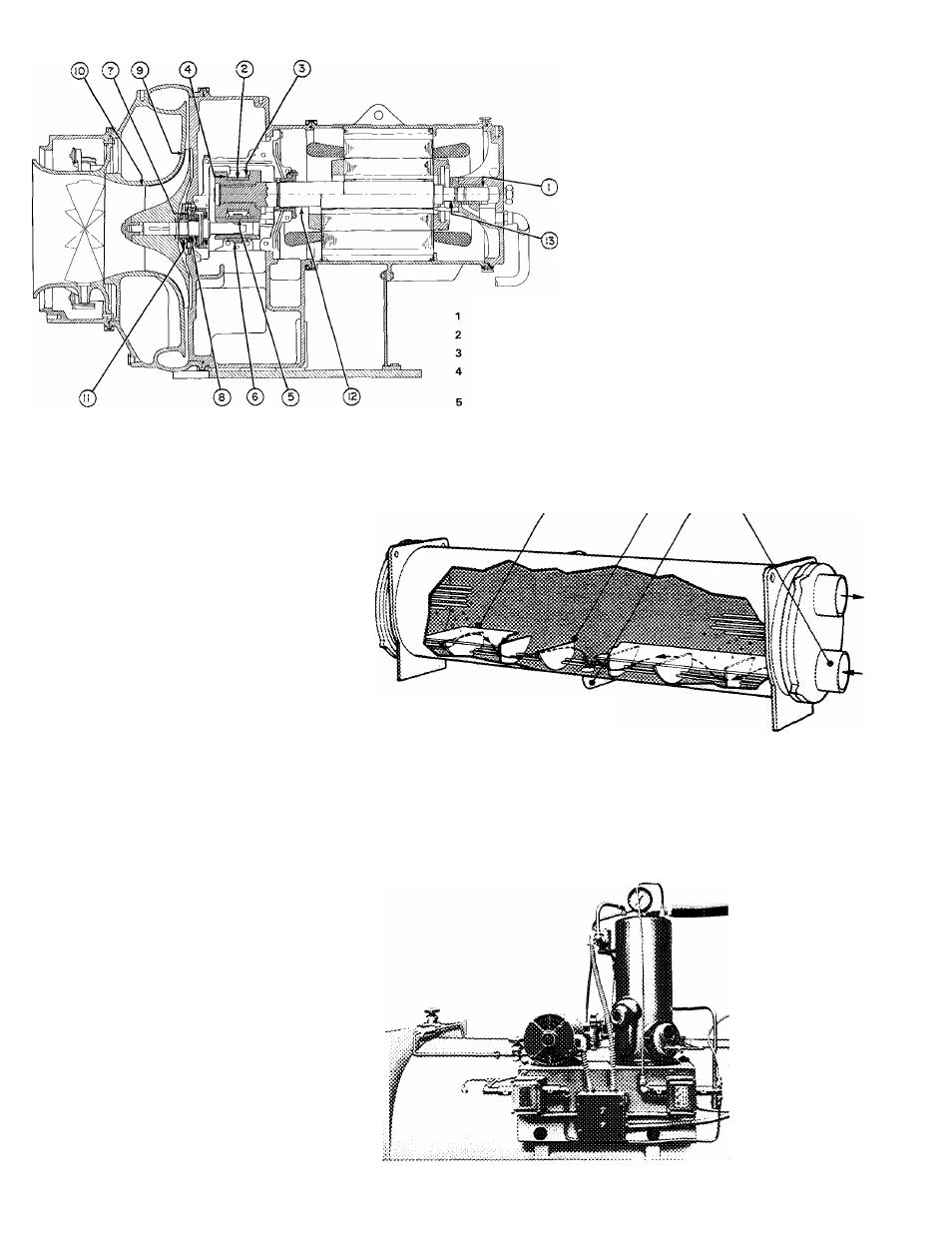
In-line impeller design
In-line impeller design, with diaphragm
between stages, allows for more flexi
bility in compressor component selec
tion, which results in first cost savings
on other machine components. Also
provides higher head capabilities, pre
vents uneven loading and allows for
routine, easy maintenance.
LEGEND
19DH
Flash and thermal economizer
Two-stage models thru 1,600 ton
(5627 kW) capacity feature a thermal
economizer. The thermal economizer
shown brings warm condensed refriger
ant into contact with the inlet (coldest)
water tubes where water as low as 55 F
(13 C) may be flowing. This low tem
perature water subcools the refrigerant
so when it moves on in the cycle it
has greater cooling potential, thus im
proving cycle efficiency and reducing
power/ton requirements. In addition, all
two-stage models employ a flash econo
mizer, not shown, to further improve
cycle efficiency. The liquefied refrig
erant leaves the condenser thru a
metering device and flows into the flash
economizer where the normal flashing
of part of the refrigerant into vapor is
used to cool the remaining refrigerant.
The flash vapor is diverted directly to
— Motor End Bearing
8
— High-Speed Journal Bearing
— Gear Journal Bearing
9
— Front of Impeller to Volute Wall
— Driving Gear Bearing To Housing
10
— Impeller Eye to ID of Inlet Ring
— Thrust Clearance on Gear
Bearing (each side)
11
— Labyrinth Behind Impeller to
Spacer Ring
— Pinion Gear Journal Bearing
— Pinion Gear Bearing To Housing
12
— Labyrinth Behind Transmission
and Motor Shell
— Thrust Bearing
13
— End-Bell Bearing Labyrinth
14 *5
J6 17
19FA THERMAL ECONOMIZER
the compressor’s second stage so that it
does not have to be pumped thru the full
compression cycle. The flash econo
mizer generates savings and signifi
cantly lowers operating costs.
LEGEND
14
— Thermal Economizer Partition Plate
15
— Refrigerant Flow Baffle
16
— Refrigerant Liquid Drain Line
17
— Condenser Water Inlet
Thermal purge
The thermal purge effectively removes
air, water, and noncondensables from
the refrigerant system, promoting
greater operating efficiency and lower
maintenance costs. It needs no water
connections or air-cooled condenser.
It performs normal system purging
during periods of operation on R-11 and
R-114 machines. In addition, on R-11
machines it doubles as a pump for leak
testing or machine evacuation after
servicing. It also provides recovery of
refrigerant
under
normal
purging
conditions.
19DH