Dimensions, 19dh – Carrier 19 Series User Manual
Page 37
Attention! The text in this document has been recognized automatically. To view the original document, you can use the "Original mode".
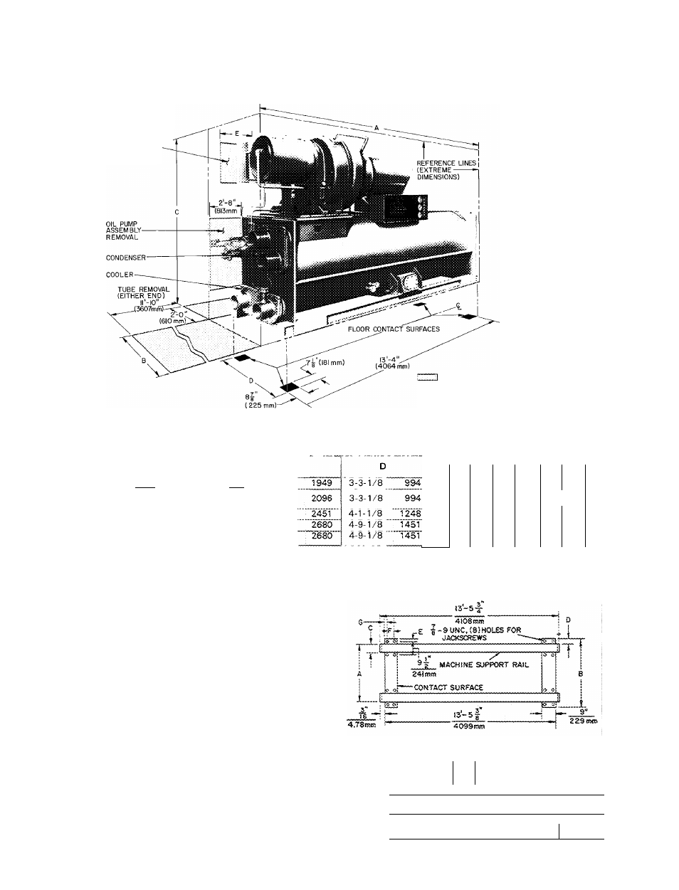
Dimensions
19DH
MOTOR STATOR AND
ROTOR REMOVAL
(SEE SERVICE
CLEARANCE FOR
MOTORS TABLE)
SPACE FOR SERVICE
AND ACCESS
ALLOW 2'-0"(6IOmm) MIN
CLEARANCE ALL AROUND
UNIT
Certified dimension drawings available on request
II.
UNISHELL
SIZES
19DH
42,44,46 ’
50,51,53,
55,57
61,63,65
71,72;73
76
.
77,78
Length*
A
14-3-3/4
14-3-3/4
14-3-3/4'
14-3-3/4'
14-3-3/4'
4362
4352
"4362
4352
4352
DIMENSIONS (ft-in.) (mm)
Width
B
3- 7-1/4
3- 7-1/4
4- 5-1/2 ■
4-11-1/4 '
4-1 i-1/4'
1099
1099
'Ts'sé''
Height
6- 4-3/4
1505
1505
6
-
10
-
1/2
8- Т-М/2
8- 9-1/2
8- 9-1/2'
NOZZLE SIZE (in.)
Cooler Passes ^ Condenser Passes
1
..2 '
3
4 ■ ■ 1
2" "'
3
'
6
4
—
—
6
4
—
8
6
6
—
8
6
4
8
6
6
6
io
8"
“6"
10
8
8
6
10
8
6
8
8
6
Ì2
10
'8'
‘Length shown is chiller with nozzle on drive end only For length with nozzles at both ends, add 6-1/4 in (159 mm)
SERVICE CLEARANCE FOR MOTORS (ft-in.)
MACHINE CONTACT SURFACES WITH
OPTIONAL SOLEPLATES
DESIGN
CENTER
VOLTAGES
208,230,
460,575
2400 & 4160
SIZE
Unishell
4i2 thru 65
50 thru 78
50 thru 78
6lThru'78
Cornpr I Motor
i 2 thru 38 I AA thru AE
.........AE
43 thru 68
72 thru 98
43 thru ës
72 thru 98
CB thru CL
CD thru CQ
CLEARANCE
_ .....................
(in.)
1-1
330
1-3-1/4
387
CA thru CL '
- ,
„
B c5 thTë'ë^2-°;^
Service access should be provided per ANSI Standard B9.1, NFPA
70 (NEC) and local safety codes Clear space adequate for inspec
tion, servicing and rigging of all major components of the chiller is
required Selected component removal spaces, with no allowance
for access or rigging are shown in phantom
UNISHELL
SIZE*
19DH
DIMENSIONS (ft-in.) (mm)
42-57
61-65
71-78
r^Al
B
C
D
E
F
G
i 3-10
3-8
0-4
0-4 0-1-1/2
0-4 0-2-1/2
; 914
1118 102
102
;
38
102!
64
^ 3-11
4-5
0-5
0-3' 0-1-1/2
0-6' 0-1-1/2
: 1194 1346 127
76
38
152!
38
i 4- 7
5-1
0-5
0-3
0-1
0-5
0-2
Ì1397
1549 127
76
25
127
50
*See machine informative plate
38