19eb, Machine contact surfaces with optional soleplates – Carrier 19 Series User Manual
Page 38
Attention! The text in this document has been recognized automatically. To view the original document, you can use the "Original mode".
19EB
{225 mm)
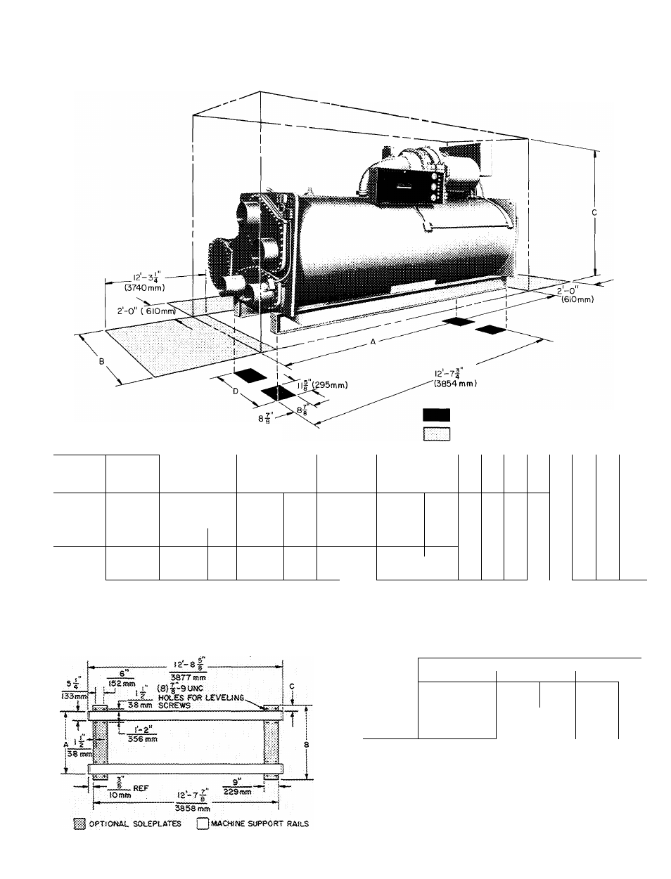
Certified dimension drawings available on request
FLOOR CONTACT SURFACE
SPACE FOR SERVICE AND ACCESS
COMPR
SIZE
UNISHELL
SIZE
19EB
Length
A*t
DliyiENSIONS (
Width
B
ft-in.J (mm)
Height
ct
D
C(
"l
wier
2
N02
’asse
3
;ZLE
s
4
SIZE
Cor
(in,:)
dense r Pas
3
ses
4
71,72 ^
14-1
4293
6- 1-1/2
1867
8-0
2438
3- 4-3/8
1026
10
8
6
6
10
"^8
8
6
73,75
14-1
4293
6- 5-1/2
1969
8-4
2540
3- 6-3/8
1076
10
8
8
6
12
10
8
8
76,77
14-1/2
4305
6-8
2032
8-6
2591
3-10-3/8
1178
12
8
8
6
12
10
8
8
81,82,83
14-1
4293
7-10-3/4
2407
9-0
2743
4- 2-1/2
1283
14
10
10
6
16
12
10
10
85,87
14-1-1/4 : 4299
8- 2-1/2
2502
9-3
2819
4- 6-5/8
1387
16
12
10
8
16
12
10
10
89
14-0
4267
8- 4-3/4
2559
9-6
2896
4-10-1/2
1486
16
12
12
8
16
12
12
12
81,82,83
14-1
4293
7-10-3/4
2407
9-3
2819
4- 2-1/2
1283
Ì4
10
To
6
“T6
lo^^
10
51-89
85,87
14-1-1/4 : 4299
8- 2-1/2
2502
9-6
2836
4- 6-5/8
1387
16
12
10
8
16
12
10
10
89
14-0
4267
8- 4-3/4
2559
9-9
2972
4-10-1/2
1486
16
12
12
8
16
12
12
12
*IVIachine length including nozzles on one end Add 8 in (203 mm) if
nozzles are on both ends
fWith high-voltage(2400-4160 v)terminal box, add 1 ft-2 in (356 mm)
to dimension A if any nozzles are on suction end (shown) Add 6 in
(152 mm) only, if suction-end water boxes are blank
^Subtract 1 ft-1 in {330 mm) from height on high-voltage (2400-
4160 v) machines
MACHINE CONTACT SURFACES WITH OPTIONAL SOLEPLATES
UNISHELL
DIMENSIONS (ft-in.) (mm)
SIZE*
A
B
C
71,72
2-10
864
3-10
: 1168
^ 0-6
152
73,75
3- 0
914
4- 0
: 1219
0-6
152
76,77
3- 4
1016
4- 4
i 1321
0-6
152
81,82,83
3-8-1/8
1121
4-7-7Z8
1413
0-5-7/8
143
85,87
4-0-1/4
1226
5- 0
1524
0-5-7/8
149
89
4-4-1/8
1324
5-3-7/8
1622
0-5-7/8
149
*See machine informative plate
Service access should be provided per ANSI Standard B9 1, NFPA 70
(NEC) and local safety codes. Clear space adequate for inspection,
servicing and rigging of all major components of the chiller is required
Selected component removal spaces, with no allowance for access or
rigging are shown in phantom
39