Electrical data (all models), Compressor motor controllers, Capacitors – Carrier 19 Series User Manual
Page 42: Electrical data, All models)
Attention! The text in this document has been recognized automatically. To view the original document, you can use the "Original mode".
Electrical data
(all models)
CONTROL TRANSFORMER REQUIREMENTS
MODEL
Standard Met
19DH
19EB J 19FA
^ANsTc89 1/NEMA Slf
Control Circuit
Inrush va
1800
1800
390*
Sealed va
550
550
270*
Purge System
Inrush va
3014
—
—
Sealed va
528
—
—
Oil Heater
Inrush va
1000
1500
1000
Sealed va
—
—
1000
19CB
511
133
44
27
750
‘Values shown are for electronic control circuit Values for pneu
matic control circuit are Inrush va, 350, Sealed va, 250
NOTE Oil heater must be on separate circuit providing continuous
service
Compressor motor controllers
Compressor motors as well as controls and accessories
require the use of starting equipment systems specifically
designed for 19 Series chillers. Refer to Application Data,
Starting Equipment publications or consult Carrier regard
ing design information for selection of controllers.
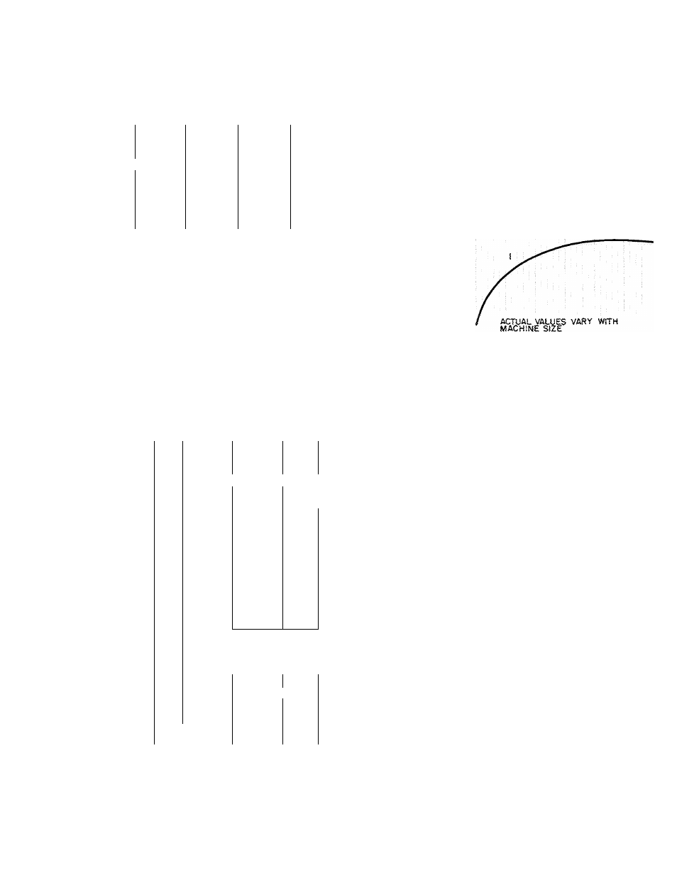
Capacitors
Power factor considerations may indicate use of capaci
tors Properly sized capacitors improve power factors as
illustrated in the Typical Power Factors curve
However, the P.F. of Carrier are so high that correc
tion is usually not necessary.
q
;
o
o
<
ce
LU
o
Q.
I 00
0 95
0 90
0.85
< 0 80
o
Q.
>-
0.75
070
TYPICAL POWER FACTORS
©UNCORRECTED POWER FACTOR
©MAX POWER FACTOR CORRECTION
25
50
75
100
PERCENT OF RATED MOTOR Kw
ELECTRICAL DATA
ITEM
OIL PUMP
19DH
19EB
19FA
19CB
PURGE PUMP
19DH^
PUMPOUT
COMPRESSOR
19EB
19FA
19CB
DESIGN
SUPPLY
VOLTAGE
FULL
LOCKED
HP
CENTER
LOAD
ROTOR
VOLTAGE
AMPS
AMPS
3-Phase, 60-Hz
220
200-240
1
6
11 5
1/2
430
380-480
9
5 62
575
550-600
6
4 55
220
200-240
3 52
27 8
1
430
380-480
1 77
134
575
550-600
1
28
9 62
220
200-240
52
28 2
1
-1/2
430
380-480
2
6
133
575
550-600
2
1
107
—
208-220
2
2
1/2
—
440-480
1
1
—
550
0.9
—
1/6
—
1-Phase, 60-Hz
115 1 44
-
3-Ph, 60-Hz
208
—
8
8
48 5
2
230
—
7 6
43 0
460
—
3.8
22 5
208
—
88
48 5
2
230
—
7 6
43 0
460
- -
3.8
22.5
220/240 v
Data available on request
NOTES:
Listed motor voltages are design voltages Motors are suitable
for use with supply voltages as noted, and will operate satis
factorily at 10% below the minimum and at 10% above the
maximum supply voltage
200
v — for use on 200- to 208-v systems
230 V — for use on 220- to 240-v systems
380 V — for use on 360- to 400-v systems
460 V — for use on 440- to 480-v systems
575 V — for use on 550- to 600-v systems
2400
V
— for use on 2300- to 2500-v systems
41 60 V — for use on 4000- to 4300-v systems
6900 V — for use on 6600- to 7200-v systems
To establish electrical data for your selected voltage, if other
than listed voltage, use the following formulas
FLA
listed FLA x
OLTA = listed OLTA x
LRA
listed voltage
selected voltage
listed voltage
selected voltage
selected voltage
listed LRA
listed voltage
EXAMPLE Find the full load amperage for a motor listed at
1 12 amps per kw input and 550 volts
575
FLA = 112
X-
— = 1 17
550
LEGEND:
FLA — Full Load Amps per kw input
LRA — Locked Rotor Amps
OLTA — Overload Trip Amps (= FLA x
1
08)
43