Carrier 50DL User Manual
Page 7
Attention! The text in this document has been recognized automatically. To view the original document, you can use the "Original mode".
L3
~r~
L2
LI
I
I I
FIELD POWER
SUPPLY
MAIN POWER TERMINAL
BLOCK IN UNIT CONTROL
BOX OR HEATER
COMPARTMENT
NOTE Subbase not used
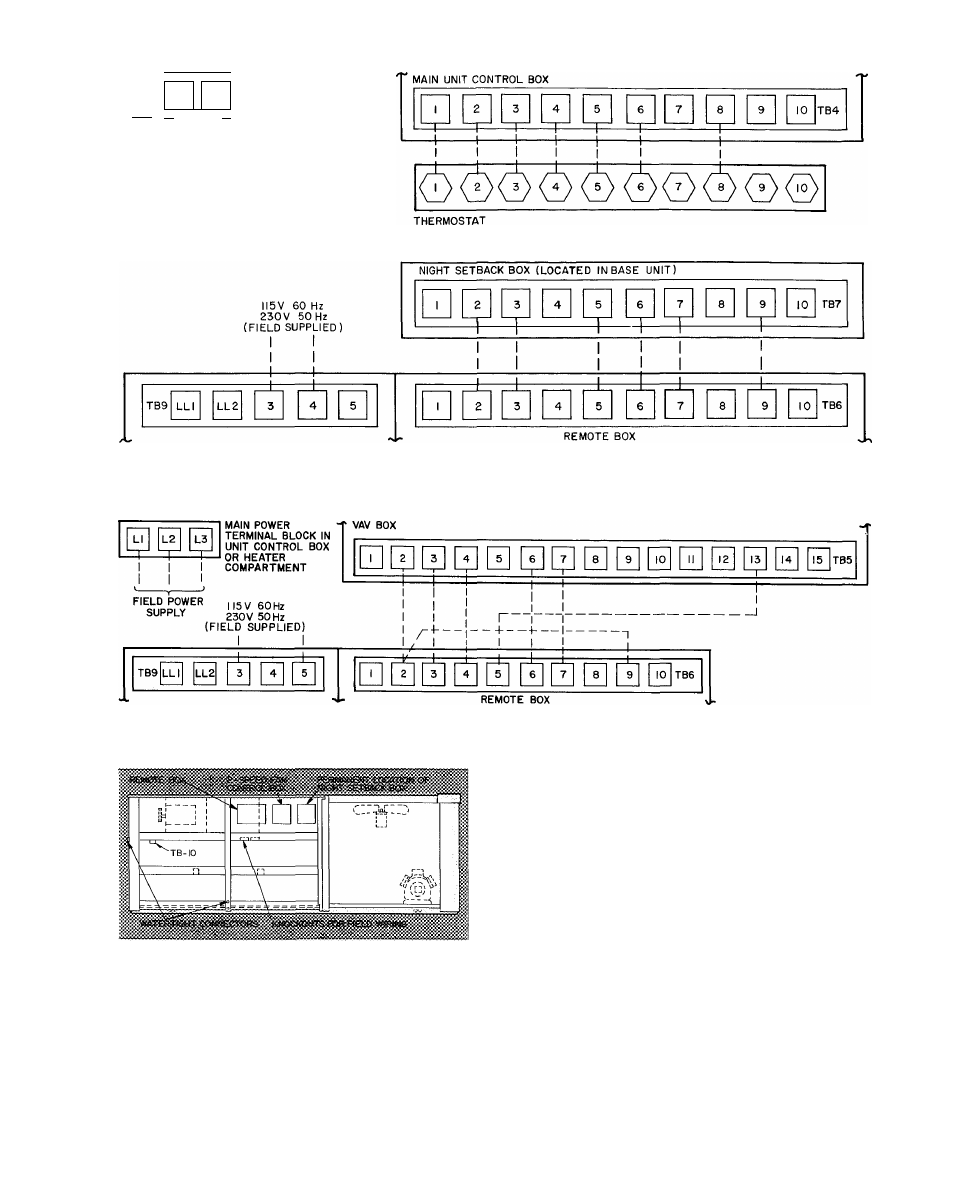
Fig. 9 — Field Wiring Connections
Constant Volume Unit With Energy Management Option
Fig. 10 — Field Wiring Connections for 50DL VAV
Fig. 11 — Shipping Location — Remote Box
UNITS WITH VARIABLE VOLUME OPTION
— Units do not use room thermostats or sensors.
In addition to the main control box, units are
equipped with a remote box and a variable volume
box. Remote box is described above (Units With
Energy Management Option). The variable volume
box (Fig. 12) contains a microprocessor, a morning
warmup thermostat, a time-delay relay, 3 unloader
relays, an interlock relay, a night relay, a day relay
and a terminal block for field wiring. Shipping loca
tion of remote box is shown in Fig. 11.
1. Remove the remote box and mount in a restricted
access area (indoors or in a weathertight space).
2. Run separate 115-volt, 60-Hz (230-volt, 50-Hz)
power to the remote box per Fig. 10. Use no. 14
AWG wire or larger and proper electrical con
nector (field supplied).
3. Run 24-volt wires between remote box and
variable volume box per Fig. 10. Use no. 18 AWG
wire for lengths up to 100 feet. Run wire in con
duit to unit if local codes dictate. Knockouts are
provided in the variable volume box and the fan
deck separating heating section from section con
taining the variable volume box (Fig. 11). Water
tight connectors are installed in unit cornerpost
and side of unit. Two rubber grommets are
shipped taped inside variable volume box. Use
grommets in knockouts in fan deck and variable
volume box.
288