Carrier 50DL User Manual
Page 2
Attention! The text in this document has been recognized automatically. To view the original document, you can use the "Original mode".
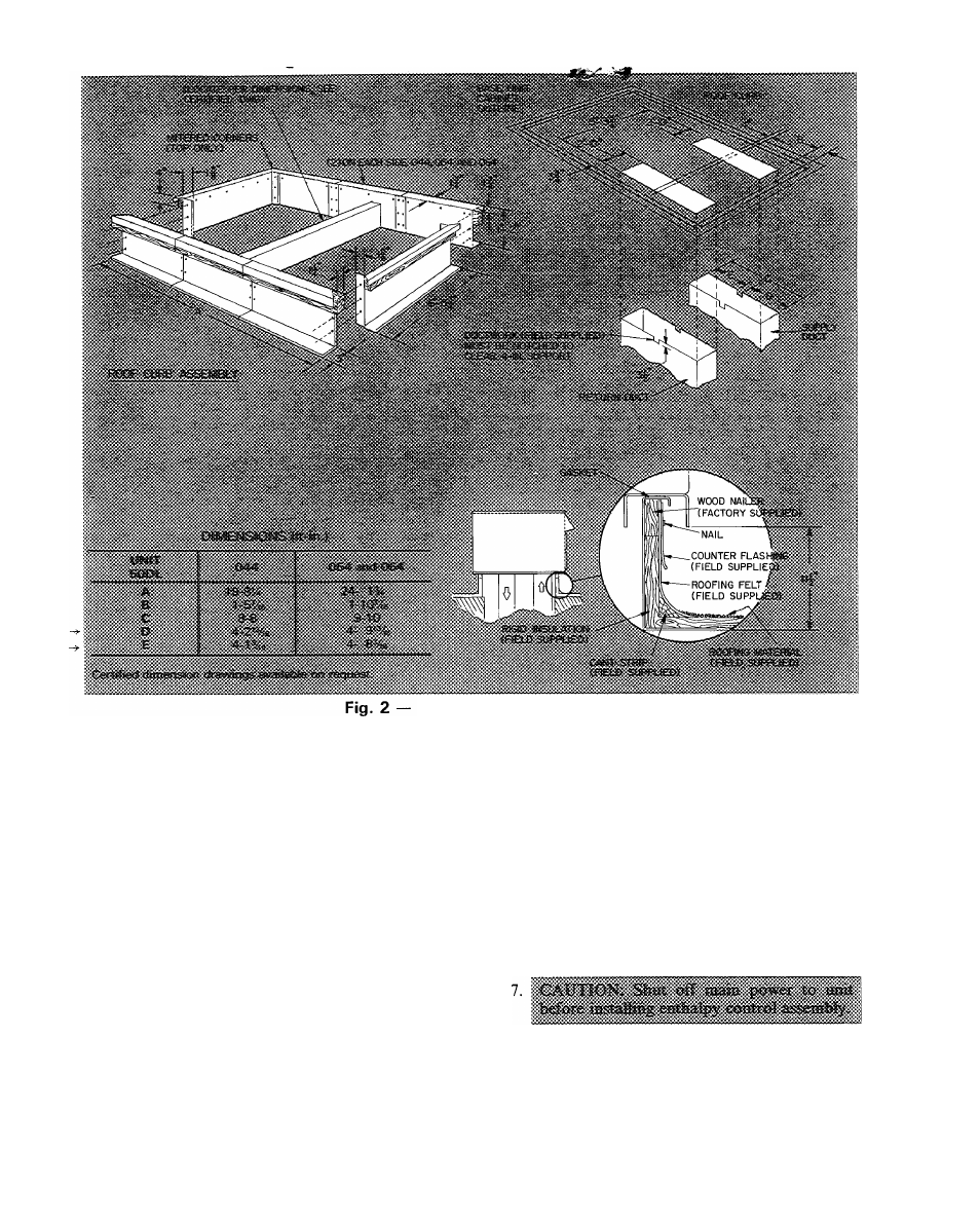
Roof Curb Dimensions
Insulate ducts passing thru unconditioned spaces
and cover with a vapor barrier.
Maintain one-in. minimum clearance between
supply air duct and any combustible material for at
least 3 ft of duct run from unit.
Unit is shipped set up for thru-the-bottom duct
connections. Ductwork openings are shown in
Fig. 4.
Economizer Section
ECONOMIZER HOODS INSTALLATION (Fig.
5) — The economizer mechanism and all electrical
connections are factory installed and adjusted
except as noted below. Hood assembly, outdoor air
inlet screens and required hardware are shipped
separately and must be field installed. Units have 2
hood assemblies.
Install economizer hoods and enthalpy control
as follows:
1. Loosen unit top panel sheet metal screws above
outdoor air inlet opening.
2. Assemble hood top panel, side panels and
support channel.
3. Insert hood flange between unit top panel flange
and unit. Slots are provided in hood flange to
clear sheet metal screws. Tighten sheet metal
screws. Apply RTV sealant to surfaces as shown
in Fig. 5.
4. Secure hood side panels to outdoor air opening
flanges, using screws provided.
5. Install hood support bracket(s) between U-
channel and support channel.
6. Install screen retainer on support channel,
using screws in the slots. Do not tighten.
8. Remove enthalpy control assembly from ship
ping location on horizontal deck in return air
filter compartment.
9. Using 4 no. 10-1/2 screws from envelope in con
trol assembly junction box, mount enthalpy
control assembly to inside of economizer hood
side panel nearest condenser section (Fig. 4).
288