Field control wiring – Carrier 50DL User Manual
Page 3
Attention! The text in this document has been recognized automatically. To view the original document, you can use the "Original mode".
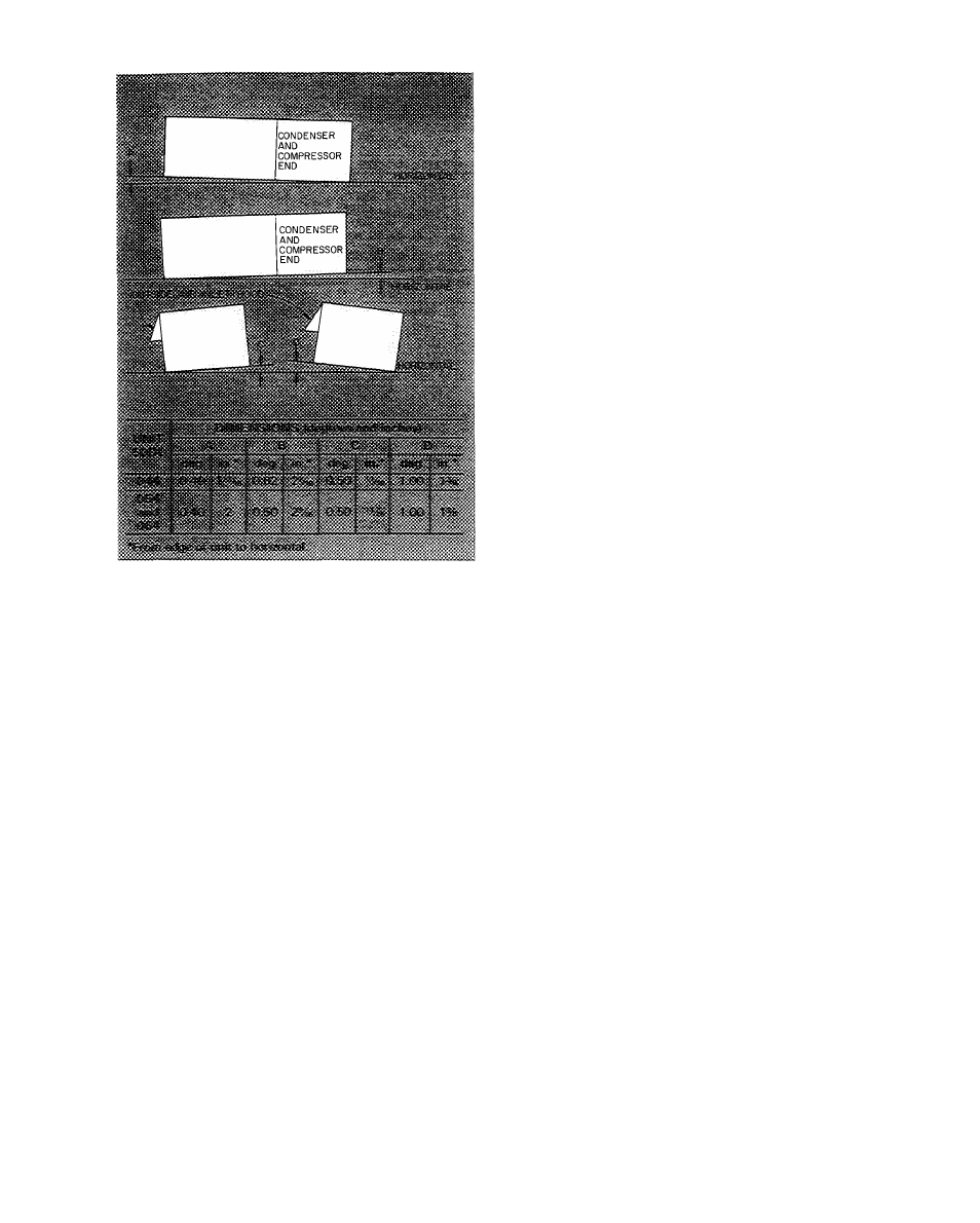
Fig. 3 — Unit Leveling Tolerances
10. Route the red and yellow wires thru knockout in
side plate. Wrap end of blue wire with electrical
tape. Using wire connectors from envelope in
junction box, wire enthalpy control assembly as
shown in Fig. 6. Use strain reliefs from envelope
on side plate and junction box.
11. Install outdoor air screens.
12. Push retainer snugly against screens and tighten
screws.
Exhaust Air Hood Installation
— The optional
power exhaust package hood damper assemblies
and required sheet metal screws are shipped in the
compartment at right of indoor air fan motor com
partment. Using screws provided, install a hood
damper assembly over each exhaust air opening as
shown in Fig. 4. Power exhaust is applied only to
economizer units using bottom duct connections.
Exhaust fan and motor assembly is factory wired
and adjusted. Refer to Service, Power Exhaust
Air Fan Adjustment if required.
Indoor Air Fans
— The fan belt and pulleys are
factory installed and adjusted. If required, adjust
as described in Service, Indoor Air Fan Adjustment.
Condensate Drains
— See Fig. 4 for drain loca
tions. Condensate drain is open to atmosphere and
must be trapped. Install a trapped drain line at con
nection to be used. Trap must be at least 3in. deep
and made of flexible material or be installed to pre
vent freeze-up.
Condensate drain pan under unit is fitted with a
one-in. FPT coupling. A gasket is shipped taped to
this drain. Install gasket in unit basepan opening or
alternate opening on end of unit.
Field Power Supply
— Unit is factory wired for
voltage shown on nameplate. The main power ter
minal block is suitable for use with aluminum or
copper wire. Units have circuit breakers for com
pressors, fan motors and control circuit. If required
by local codes, provide an additional disconnect
switch.
If an external electrical source is used, unit must
be electrically grounded in accordance with local
codes, or in the absence of local codes, with the
National Electrical Code, ANSI Cl-1978.
All field wiring must comply with National Elec
trical Code and local requirements.
Install conduit connector in unit basepan or side
panel openings provided as shown in Eig. 4. Route
power lines thru connector to terminal connections
in control box as shown in Fig. 8, 9 and 10.
Affix crankcase heater sticker to unit disconnect
switch.
Voltage to compressor terminals during com
pressor operation must be within voltage range
indicated on unit nameplate. Also, see Tables 2 and
3. Phases must be balanced within 2%. Contact local
power company for correction of improper voltage
or phase unbalance. Failure due to operation of unit
on improper line voltage or with excessive phase
unbalance constitutes abuse and may cause damage
to unit electrical components.
Field Control Wiring
STANDARD
UNIT
(WITHOUT
ENERGY
MANAGEMENT OPTION) — Install a Carrier-
approved accessory electronic thermostat on a sub
base (or a transmitter on subbase if remote sensor is
used) per installation instructions included with the
accessory. Note that the subbase must be used oh
constant volume units without night setback. Locate
thermostat, or remote sensor, if used, in the condi
tioned space where it will sense average temperature.
Route thermostat cable or equivalent single leads
of no. 18 AWG colored wire from subbase terminals
thru connector on unit to low-voltage connections
in main control box as shown on unit wiring dia
gram and in Pig. 8.
UNITS
WITH
ENERGY
MANAGEMENT
OPTION — In addition to the standard control
box, units with Energy Management option are also
equipped with a remote box and a night setback
box. The remote box contains a 7-day time clock,
a bypass switch that can manually bypass the time
clock for up to 5 hours, 6 indicator lights and 2
terminal blocks for field wiring connections. Mount
this box remote from the unit in an indoor or