Carrier 50DL User Manual
Page 13
Attention! The text in this document has been recognized automatically. To view the original document, you can use the "Original mode".
m
As the conditioned space temperature approaches
the thermostat’s cooling set point, stages cycle off,
last stage first. After all stages of mechanical
cooling are off, economizer modulates to minimum
position.
During the cooling cycle, a discharge air sensor
senses discharge air temperature. If discharge air
temperature drops below 62 F, the economizer
modulates toward minimum position. At 50 F dis
charge temperature, the economizer will be at mini
mum position.
At the end of the DAY (OCCUPIED) mode on
the clock, unit controls enter the NIGHT (UN
OCCUPIED) mode. Economizer closes. Indoor air
fan runs only on a call for heating or cooling. Tem
perature controls go into HEATING SETBACK,
COOLING SETUP or COOLING SHUTDOWN
mode.
HEATING SETBACK is field selectable at the
unit for 5°, 10°, or 15° below set point on room
thermostat.
COOLING SETUP is field selectable at the unit
for 5°, 8°, or 12° above set point on room
thermostat.
During the UNOCCUPIED mode, unit continues
to use economizer cooling first and then integrates
economizer cooling with mechanical cooling to
meet cooling requirements.
A 5-hour bypass timer is located in the remote
control box to provide air conditioning during
normally unoccupied hours.
TWO-SPEED INDOOR FAN OPTION — Table 1
lists the 2-speed indoor fan motor hp, frame size and
shaft diameter. Due to the larger frame size, the
208/ 230-volt, 25-hp motors and all 30-hp motors are
available in single speed only.
The 2-speed motors are 2 winding (4 pole/6 pole)
design, with speeds of 1750/1170 rpm. Indoor fans
automatically operate at low speed until high speed
is necessary to maintain comfort conditions. No
field wiring or adjustment is necessary.
COOLING mode sequence of operation is out
lined in Table 4.
In HEATING mode, the indoor fan operates at
low speed for ventilation only, and operates at high
speed during active heating. A 2-heat/4-cool logic
panel provides the necessary fan control.
The circuit breakers, contactors, and relays re
quired for 2-speed motor control are located in the
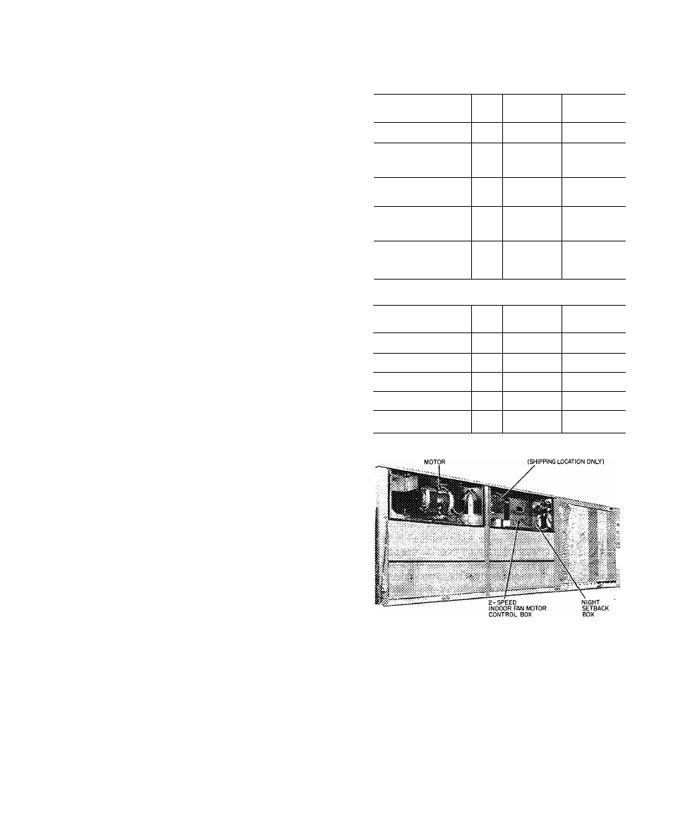
2-speed indoor fan motor control box (Fig. 17).
POWER EXHAUST OPERATION — Units have
an auxiliary switch located on the damper motor.
This switch is factory set to prevent the power
exhaust fans from operating when the economizer
damper is less than 30% open.
If other than factory setting is desired, adjust
as follows:
Table 4 — Two-Speed Indoor Air Fan
Staging; Cooling Mode
ECONOMIZER COOLING (Enthalpy Permitting)
OPERATING
CONDITION
FAN
SPEED
ECONOMIZER
DAMPER
POSITION
COMPRESSOR
OPERATION
NO CALL FOR COOLING
(Ventilation Air)
Low
Minimum
Position
Off
CALL FOR
MINIMUM COOLING
Low
Modulating
Between
Min and
Full Open
Off
STAGE 1 OF
LOGIC PANEL
(Economizer Cooling)
High
Full Open
Off
STAGE 2 OF
LOGIC PANEL
(Integrated Econ/Mech
Cooling)
High
Full Open
Compr 1
STAGE 3 AND 4
OF LOGIC PANEL
(Integrated Econ/Mech
Cooling)
High
Full Open
Compr 1 and 2
MECHANICAL COOLING
(Enthalpy Not Permitting Economizer Cooling)
OPERATING
CONDITION
FAN
SPEED
ECONOMIZER
DAMPER
POSITION
COMPRESSOR
OPERATION
NO CALL FOR COOLING
(Ventilation Air)
Low
Minimum
Position
Off *
STAGE 1 OF
LOGIC PANEL
Low
Minimum
Position
Off
STAGE 2 OF
LOGIC PANEL
Low
Minimum
Position
Compr 1
STAGE 3 OF
LOGIC PANEL
Low
Minimum
Position
Compr 1 and 2
STAGE 4 OF
LOGIC PANEL
High
Minimum
Position
Compr 1 and 2
INDOOR FAN
REMOTE CONTROL PANEL
Fig. 17 — Two-Speed Fan Control Box
Location
NOTE: Adjustment does not require running the
motor.
1. Motor must be in the fully closed position.
2. Referring to Fig. 18, take off “C” clip and drive
bracket. Remove screws at 4 corners of housing.
Pull off return spring housing.
3. Remove spring on motor shaft.
4. Adjust switch as shown in Fig. 19.
5. After adjustment, replace spring on motor shaft
and reassemble return spring housing.
13