Service – Carrier 50DL User Manual
Page 16
Attention! The text in this document has been recognized automatically. To view the original document, you can use the "Original mode".
pressor automatically restarts after a 5-minute inter
val. If compressor shutdown is due to tripped over
loads, the circuit breakers must be manually reset
before compressor will start.
Timer (Time Guard®) for second compressor has
a 6-minute interval to prevent compressors from
starting simultaneously.
Refer to unit label diagram for specific timer
sequence.
CRANKCASE HEATER — Unit main power
supply must remain on to provide crankcase heater
operation. Crankcase heater in each compressor
keeps oil free of refrigerant while compressor is off.
HEAD PRESSURE CONTROL — Each unit has a
fan cycling thermostat to shut off 2 outdoor fan
motors at 55 F. This permits unit to operate with
correct condensing temperatures down to 35 F out
door air temperature.
SERVICE
Electronic Component Checkout
CONSTANT VOLUME UNITS
The checkout procedures in this section will
determine whether;
1. The logic panel is controlling the heating and
cooling equipment properly.
2. System components are correctly wired to the
logic panel.
Prior to checking out control circuit, establish
setting on the low ambient lockout thermostat.
Compressors will not start below this setting (cool
ing mode only). Recommended setting is approxi
mately 50-55 F.
NOTE: To complete the electronic component
checkout, a volt-ohmmeter (Simpson 260 is
recommended) is required.
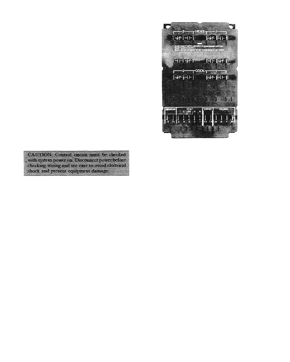
LOGIC PANEL (Fig. 21)
1. Check that 24 VAC is supplied to logic panel.
Connect meter to terminals TR.
2. Check thermostat supply voltage at STAT ter
minals 1 and 2. Reading should be 20 VDC.
3. Remove thermostat supply wires from STAT
terminals 1 thru 5 on logic panel.
4. Set meter to volts AC scale equal to relay switch
ing voltage (50-volt scale for 24 VAC).
5. To simulate a call for cooling, jumper between
STAT terminals 2 and 4. Normally open Logic
Panel contacts (Cool 1 and 2) should close and
cooling equipment should cycle on.
6. Connect meter leads to the normally open cool
ing contacts 1 and 2 on logic panel. Meter should
Fig. 21 — Logic Panel
read zero if contacts have closed and contacts
are made.
If meter is reading zero and cooling equipment
has not cycled on, logic panel is not at fault.
7. To simulate a call for heating, jumper between
STAT terminals 2 and 5. Normally open logic
panel contacts (HEAT 1 and 2) should close and
heating equipment should cycle on.
8. Connect meter leads to the normally open heat
ing contacts on logic panel. Meter should read
zero if contacts have closed.
If meter is reading zero and heating equipment
has not cycled on, logic panel is not at fault.
9. Replace thermostat wiring to terminals 1 thru 5.
DISCHARGE SENSOR
1. Set resistance on meter to R x 100.
2. Disconnect lead from SENSOR terminal T1 on
logic panel.
3. Connect one meter lead to logic panel terminal T
and the other meter lead to the loose lead wire
from the sensor.
4. Meter readings depend on temperature. Dis
charge sensor readings should be between 1500
and 4500 ohms. See Fig. 22.
THERMOSTAT/TRANSMITTER (Fig. 16)
1. Set meter to 20 VDC scale.
2. Check for power to thermostat. Connect negative
(-) lead to terminal 1 and positive (+) lead to
terminal 2. Meter should read 20 VDC.
3. Connect the negative (-) lead to terminal 1 and
the positive (+) lead to terminal 4.
4. Slowly move the cooling lever below room tem
perature to simulate a call for cooling. Meter
16