Initial start-up, Sequence of operation – Carrier WEATHERMASTER III 38HQ User Manual
Page 9
Attention! The text in this document has been recognized automatically. To view the original document, you can use the "Original mode".
FACTORY WIRING
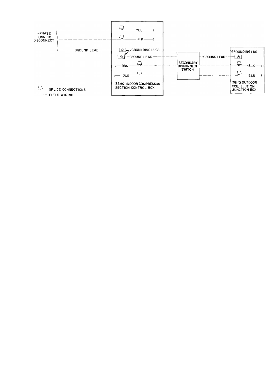
Fig. 8 — Line Power Connections
INSTALL A BRANCH CIRCUIT DISCONNECT
PER N.E.C. of adequate size to handle compressor
section starting current. Provide a separate dis
connect switch for outdoor coil section. Provide a
separate disconnect for indoor fan-coil and for each
accessory electric heater circuit as required. (See In
door Unit and Electric Heater Installation, Start-Up
and Service Instructions.) Locate disconnect(s)
within sight of and readily accessible to the units, per
section 440-14 of National Electrical Code (NEC).
ROUTE LINE POWER LEADS INTO COM
PRESSOR SECTION — Extend lead from discon
nect per N.E.C. thru 1-1/8 in. hole provided in com
pressor section top panel (Fig. 2) and into control
box. Extend line power leads for outdoor coil
section thru 7/8-in. hole provided in compressor
section top panel and into control box.
CONNECT GROUND LEADS AND POWER
WIRES — Connect ground leads to the ground lug
in control box for safety. Splice compressor section
line power leads to yellow and black pigtails, and
outdoor coil section power leads to brown and blue
pigtails. Use wire nuts and tape at each splice con
nection as shown in Fig. 8.
CONNECT POWER LEADS FROM INDOOR
COMPRESSOR
SECTION
TO
OUTDOOR
COIL SECTION thru secondary disconnect switch.
From this disconnect switch extend leads thru
hole provided in outdoor eoil section basepan
(Fig. 1) and into line voltage seetion of junction
box. Fig. 14. Splice leads to black and blue pigtails
with wire nuts.
CONNECT CONTROL WIRING (24-v) — Extend
wiring thru 7 / 8-in. grommeted hole in compressor
section top panel (Fig. 2), and to control wiring
terminal board on side of control box. Connect
leads to terminal board as shown in Fig. 7. Extend
and connect control wiring from compressor section
to outdoor coil section as required. Make splice
connections in low-voltage section of coil junction
box.
Use indoor fan-eoil transformer as 24-v supply for
system. Be sure fan eontrol package is installed as
described in Step 6. Package contains 75-va trans
former of adequate capacity to handle system
current.
INITIAL START-UP
The compressors in the indoor compressor
section are equipped with crankcase heaters. It is
reeommended that the heaters be energized a
minimum of 24 hours before starting the system. To
energize crankcase heaters only, set the thermostat
at OFF position and turn on main power to
compressor section.
To Start System
— (Be sure crankcase heaters
have been energized for 24 hours.) Adjust the ther
mostat as follows;
1. Set selector switch at OFF.
2. Turn on main disconnect switch(es) to indoor
and outdoor units.
3. Set fan switch as desired (ON or AUTO.).
4. Set thermostat dial at desired temperature.
5. Set selector switch at HEAT or COOL.
Check system refrigerant charge. See Service —
Refrigerant Charging.
SEQUENCE OF OPERATION
Fan Switch at AUTO. Position, Thermostat at
ON Position
(Crankcase heater is on as soon as the
field power supply is on.)
THERMOSTAT CALLS FOR COOLING
1. First-stage cooling thermostat (Co) closes and
the reversing valve solenoid (RVS) is energized.
The RVS actuates the reversing valve and
switches the system to cooling.
2. Second-stage cooling thermostat (Cl) closes. If
the low-pressure switch (LPS) is closed, com
pressor contactor (C) is energized and compres