Carrier WEATHERMASTER III 38HQ User Manual
Page 8
Attention! The text in this document has been recognized automatically. To view the original document, you can use the "Original mode".
Attach one lead to compressor terminal board
connection OA. Connect other lead to line side of
defrost thermostat.
Set switch at temperature of first thermal balance
point (heating). This balance point is provided by
CLIC load estimating program. Further adjust
ments can be made following operating experience.
Step 8 — Install Room Thermostat, Outdoor
Thermostat(s) and Emergency Heat Relay —
Follow Installation Instructions shipped with these
accessories plus the instructions in the sections that
follow. Connect as described in step 9.
INDOOR THERMOSTAT — Use only Carrier
indoor thermostat and subbase as shown in Table 4.
Set heat anticipator settings according to Table 5.
These settings may be changed slightly to provide
a greater degree of comfort for certain installations.
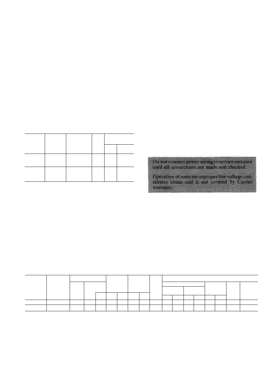
Table 5 — Thermostat Heat Anticipator
Settings
INDOOR
COMPR
SECTION
OUTDOOR
COIL
SECTION
INDOOR
UNIT WITH
ELECTRIC
HTR
HTR
KW
ANTICIPATOR
SETTINGS
First
Stage
Second
Stage
38HQ227
38HQ940
40FS160 with
40FQ916010
thru 090
8 thru
20
Fixed
16
38HQ234
38HQ960
40FS200 with
40FQ920060
thru 150
10 thru
25
Fixed
49
OUTDOOR THERMOSTAT ACCESSORY pro
vides adjustable outdoor control of accessory
electric heater (used on indoor fan-coil). This ther
mostat closes on a drop in outdoor temperature.
It energizes a stage of electric heat when the out
door temperature setting is reached, provided the
room thermostat is on the second stage of heating.
One outdoor thermostat is recommended for each
stage of electric heat after the first stage. Connect
as described in Step 9. Set the outdoor thermostats
progressively lower for each stage. Refer to heat
load of building and unit capacity to determine the
correct outdoor thermostat settings. Locate maxi
mum of 2 outdoor thermostats in control voltage
section of outdoor coil section junction box. Fasten
in place with sheet metal screws.
EMERGENCY HEAT RELAY — This accessory is
required when 2 or more outdoor thermostats are
used. It is automatically energized by the manually-
operated emergency heat switch in the indoor ther
mostat subbase. The indoor thermostat locks out
the compressor and the relay bypasses the outdoor
thermostats for electric heater operation during heat
pump shutdown. When one outdoor thermostat is
used, an emergency heat relay is not required. The
emergency heat switch in the indoor thermostat
subbase bypasses the outdoor thermostat, locks out
the compressor and activates the electric heater.
Install emergency heat relay in a convenient loca
tion on indoor unit. Attach with sheet metal screw.
Connect relay as shown in Fig. 7.
Step 9 — Make Electrical Connections
— In
stall field wiring in accordance with local and
national fire, safety and electrical codes. Be sure
voltage to units is within ± 10% of voltage indi
cated on nameplate. Contact local power company
for correction of improper line voltage.
When making electrical connections, provide
clearance at unit for refrigerant piping connections.
See Table 6 for recommended wire and fuse sizes.
Line power connections and control circuit connec
tions are shown in Fig. 7 and 8.
Route line and control power wiring for 38HQ
outdoor coil from connections in the 38HQ in
door compressor section. Use 14-ga (minimum) line
power wire size to outdoor coil section when total
wire length connecting compressor section to coil is
under 25 feet. If over 25 ft, use same wire size as
compressor section branch circuit.
Table 6 — Electrical Data
INDOOR
COMPR
SECTION
OUTDOOR
COIL
SECTION
VOLTAGE
COMPR
1
COMPR
2
OFM
(FLA)
BRANCH CIRCUIT
Nom
1-Ph
60-Hz
Operating*
Power Wire
Gnd Wire
Sizet
(AWG)
Min
Ckt
Amps
Max
Fuse
Amps“
Min Size
(AWG)
Max Ft
Max
Min
LRA
RLA
LRA
RLA
ICS
OCS
ICS
OCS
ICS
OCS
38HQ227
38HQ940
230
254
207
72
17
88
17 8
1 5
6
14t
55
25t
10
14t
40 8
50
38HQ234
38HQ960
230
254
207
88
20
94
21 2
2 3
4
14t
75
25t
10
14t
48 8
60
FLA — Full Load Amps
ICS — Indoor Compressor Section
LRA — Locked Rotor Amps
OCS — Outdoor Coil Section
OFM — Outdoor Fan Motor
RLA — Rated Load Amps
‘Permissible limits of the voltage range (for limited period of time)
at which the units will operate satisfactorily
fOutdoor coil section wiring — for 25 ft wire run or less, use
minimum 14 AWG size wire For longer wire run use same size
as supply to compressor section
^Required when using nonmetallic conduit
“Maximum dual element fuse size
NOTES;
1 All units have 24-v control circuit which requires external
power source
2 Copper wire size table based on 60 C Use copper or copper-clad
aluminum wire to indoor section; copper wire only to outdoor
section Use latest National Electrical Code for wire sizing