Pumpdown procedure (cooling cycle) — the – Carrier WEATHERMASTER III 38HQ User Manual
Page 14
Attention! The text in this document has been recognized automatically. To view the original document, you can use the "Original mode".
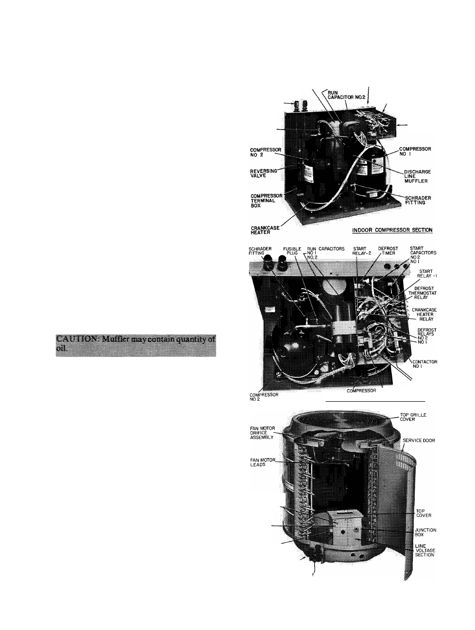
Compressor Removal
— See Table 2 for com
pressor information; Fig. 14 for component loca
tion. Shut off power to unit. Remove refrigerant
from system using refrigerant removal methods
described in Carrier Standard Service Techniques
Manual, Chapter 1, Refrigerants.
Follow safety codes, and wear safety glasses and
work gloves. Have quenching cloth available.
If either compressor fails due to motor burnout,
it is necessary to replace both compressors. Since
both compressors use common oil, one compressor
burnout contaminates both compressors.
1. Remove unit top cover and front access
wrapper.
2. Remove compressor terminal box cover, dis
connect and remove compressor power leads.
3. Using a tubing cutter, cut suction and discharge
lines at convenient place near compressor for
easy reassembly to new compressor with copper
slip couplings.
4. Disconnect equalizer tube from compressor
shell.
5. Remove crankcase heater from compressor
base.
6. Remove compressor hold-down bolts. Lift out
compressor.
7. Carefully unbraze suction and discharge line
piping stubs from compressor. If oil vapor in
piping stubs ignites, use quenching cloth.
8. Braze piping stubs (removed in step 1) onto new
compressor.
9. Clean system. Add new liquid line heat pump
filter-drier as described below.
10. Install new compressor in unit. Braze suction
and discharge lines to compressor piping stubs
(at points where cut, step 3) using field-supplied
copper couplings. Reconnect equalizer tube.
Teflon O-ring in fitting is reusable. Torque
fitting to 30-40 ft-lb. Ensure compressor hold
down bolts are in place. Connect wiring.
11. Evacuate and recharge system.
Lubrication
— Compressor contains factory oil
charge. Replace oil when lost. See Table 2 for oil
recharge. If necessary, refer to Carrier Standard
Service Techniques Manual, Chapter 1, Refrig
erants, pages 1-21, for oil recharging procedure.
Use Carrier PP33-1, Texaco Capella B or Suniso
3G oil.
Filter-Drier
— Install accessory heat pump filter-
drier (Table 4) in system liquid line when refrig
erant system is opened for service as described under
Compressor Removal. Position drier in liquid line at
convenient location.
Pumpdown Procedure (Cooling Cycle)
— The
38HQ units may be pumped down in order to make
repairs on low side of system without losing com
plete refrigerant charge.
SUCTION LINE
ACCUMULATOR
RUN, CAPACITOR
VAPOR LINE
CONNECTIONS
LOW
PRESSURE
SWITCH
CONTROL WIRE
TERMINAL BOARD
.CONTROL
BOX
SIGNAL-LOG"’
N01
N0 2
'CONTACTOR
N0.1
N0.2
INDOOR COMPRESSOR SECTION-TOP VIEW
ACCESSORY
OUTDOOR
THERMOSTAT
LOCATION
CONTROL
VOLTAGE
SECTION
DEFROST
THERMOSTAT'
LIQUID LINE SERVICE'
VALVE(WITH SERVICE PORT)
VAPOR LINE SERVICE VALVI
(WITH SERVICE PORT)
38HQ OUTDOOR COIL SECTION
Fig. 14 — Component Location
14