Carrier WEATHERMASTER III 38HQ User Manual
Page 4
Attention! The text in this document has been recognized automatically. To view the original document, you can use the "Original mode".
Insert felt isolation pad (factory supplied) be
tween unit and a level rigid mounting base to absorb
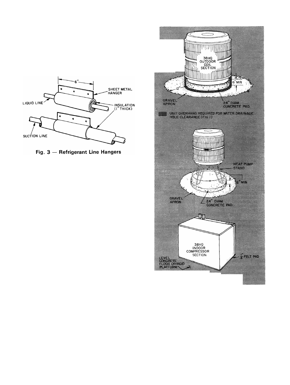
vibration. Isolate interconnecting tubing from
framing and ductwork or where tubing runs thru
stud spaces, enclosed ceilings or pipe chases. Use
isolation type hanger, Fig. 3, since rigid fastening
will transmit pulsation to structure creating ob
jectionable sound.
System Refrigerant Control consists of factory-
installed bypass-type AccuRater™ devices located
as shown in Fig. 15. These metering devices include a
replaceable orifice piston that is calibrated to
regulate refrigerant flow. Piston data is given in
Table 2. In some instances, the factory-installed
piston must be replaced by a factory-supplied re
placement
piston.
Where
required,
substitute
pistons as described in Step 5 and as indicated on
tags attached to system AccuRater devices.
Step 2 — Install Outdoor Coil Section
ON THE GROUND — Use a solid, level concrete
pad as shown in Fig. 4. Position unit so that coil
drainage holes in basepan overhang the pad. (See
Fig. 1 for drainage hole locations.) Be sure pad does
not obstruct drainage holes (water drains from holes
during heating and defrost cycles). Attach unit to
pad with 1 / 4-in. mounting bolts. Any 2 holes in unit
basepan may be used to fasten unit to pad.
Construct round, 24-in. diameter 6-in. thick pad a
minimum of 6 in. above grade to provide clearance
under holes for drainage and ice build-up. In areas
where prolonged subfreezing temperatures or snows
occur: increase clearance by using accessory heat
pump stand to support unit 12 to 18 in. off concrete
base. See Fig. 4. Be sure stand does not obstruct coil
drainage holes. Avoid mounting unit in prevailing
winds to minimize effect on defrost performance.
Construct wind break if necessary. Extend a 12-in.
gravel apron around pad for condensate and defrost
water drainage field.
Provide support bracket from structure or other
solid support to outdoor unit to give stability. Since
it is lightweight, the outdoor section may be
.
-.-.A
■ ■
Fig. 4 — Unit Support Details
mounted on a platform attached to or built out from
structure. Construct platform using drainage and
clearance recommendations above. Locate and con
struct platform to avoid possible transfer of unit
vibration to structure. See Table 2 for unit weight.
ON THE ROOF: Install a level platform or frame to
support unit. Elevate unit for proper clearance as
previously described for on-the-ground installation.
Plan roof design and water drainage to prevent unit
from sitting in water. Flash all roof openings to
prevent leaks.