Carrier WEATHERMASTER III 38HQ User Manual
Page 12
Attention! The text in this document has been recognized automatically. To view the original document, you can use the "Original mode".
charge, evacuate system to 500 microns (29.7 in.
vacuum) before recharging. Service port connec
tions are provided on indoor compressor unit
suction and discharge lines for evacuation and
charging. (See Fig. 14 for service port location.)
Dial-a-charge charging cylinder is an accurate de
vice used to recharge systems by weight. The
cylinders are available at refrigeration supply
firms.
TO CHECK AND/ OR ADJUST CHARGE DUR
ING COOLING SEASON — Use correct Cooling
Cycle Charging Chart (Fig. 10 and 11) and follow
charging chart usage method below.
TO CHECK SYSTEM OPERATION DURING
HEATING CYCLE — Use correct Heating Cycle
Operation Check Chart (Fig. 12 and 13). These
charts indicate whether a correct relationship
exists between system operating pressures and air
temperatures entering indoor and outdoor units. If
pressure and temperature lines do not intersect on
chart, the system refrigerant charge may not be
correct or other system abnormalities may exist.
Do not use Operation Check Charts to adjust
refrigerant charge. Weigh charge into system.
U S I N G C O O L I N G C Y C L E C H A R G I N G
CHARTS
1. Operate unit a minimum of 10 minutes before
checking
charge,
and
after
each
charge
adjustment.
2. Measure suction pressure by attaching a gage to
indoor unit suction service port. (See Fig. 14 for
correct service port location.)
3. Measure outdoor air dry-bulb temperature enter
ing outdoor coil. Use a service thermometer.
4. Using a sling psychrometer, measure wet-bulb
temperature of air entering indoor fan-coil
unit.
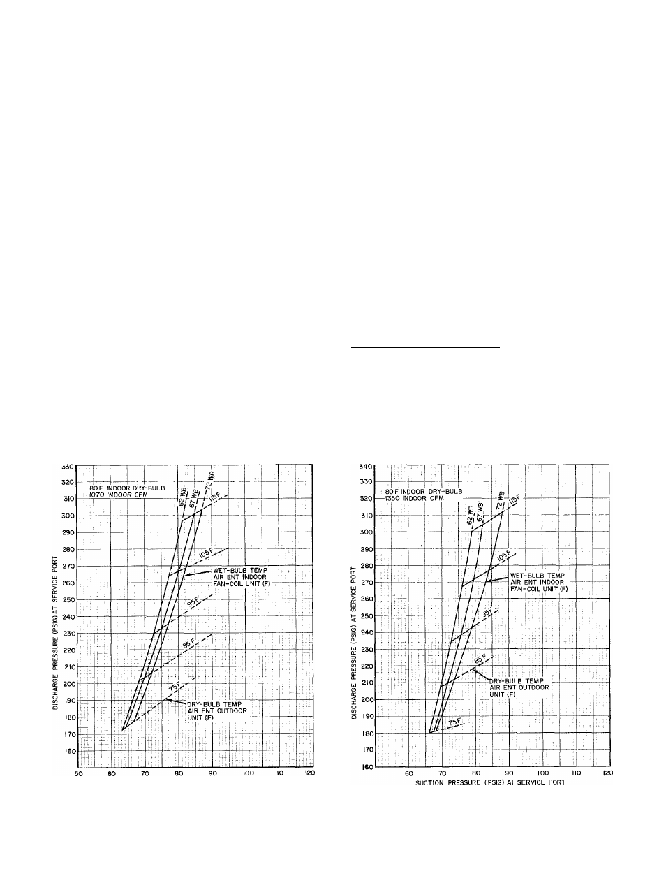
5. Refer to correct Charging Chart. Locate on
curves where outdoor air dry-bulb and indoor air
wet-bulb temperature lines intersect.
6. From intersect point, project vertically down
ward to chart suction pressure line. Compare
chart suction pressure to unit suction pressure
(Step 2).
7. If unit suction pressure is lower than chart pres
sure, add refrigerant to system until chart pres
sure is reached. If unit suction pressure is
higher than chart pressure, remove refrigerant
until chart pressure is reached.
Temporary Capacitance Boost — If necessary, see
Carrier Standard Service Techniques Manual,
Chapter 2, Electrical, for details.
SUCTION PRESSURE {PSIG) AT SERVICE PORT
Fig. 10 — 38HQ227/38HQ940 with
28VQ036/40FS160 Cooling Cycle
Charging Chart
t
Fig. 11 — 38HQ234/38HQ960 with
28VQ042/40FS200 Cooling Cycle
Charging Chart
12