Table 4 — accessories, Installation – Carrier WEATHERMASTER III 38HQ User Manual
Page 3
Attention! The text in this document has been recognized automatically. To view the original document, you can use the "Original mode".
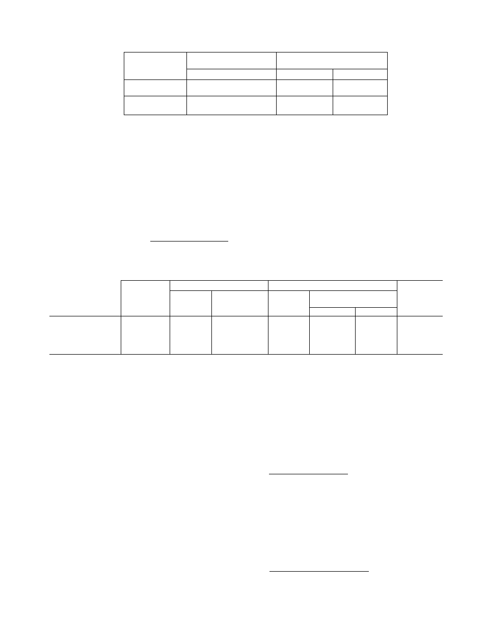
Table 3 — Heater Airflow Data
INDOOR
COMPRESSOR
SECTION
HEATER
MINIMUM ALLOWABLE
SIZE
Airflow (cfm)
Fan Speed
38HQ227
8 thru 20 kw
(40FQ91 6010 thru 090)
1150
Low
38HQ234
10 thru 25 kw
(40FQ920060 thru 1 50)
1550
Low
PART NO.
38CQ900102
38CQ900122
38CQ900132
38CQ900152
38CQ900172
38HQ900011
38HQ900002
38RQ900012
38CQ900072
38RQ900072
Table 4 — Accessories
DESCRIPTION
Six
38CQ900081
Low-voltage
Honeywell
Thermostat
(HH07AT071)
and
Thermostat
Subbase
(HH93AZ073)
with automatic changeover
Six
38CQ900111
Low-voltage
Honeywell
Thermostat
(HH07AT071)
and
Thermostat
Subbase
(HH93AZ075)
with manual changeover
Six 38CQ900091 Liquid Line Filter-Drier
Six 38CQ900141 Solid State Time Guard (24 v)
SixHH22AG110 Optimizer Control
Hot Shot Heat Reclaim Device
Six 38HQ900001 Outdoor Thermostat
Six 38RQ900001 Emergency Heat Relay
Six 38C0900061 two-packs. Flare (3/8-in ) to compatible (3/8-in ) couplings
Six 38RQ900061 Heat Pump Stand for Outdoor Coil Section
_
___
TUBING
TUBING
PACKAGE
Length
(ft)
Liquid
Suction*
COMPR
SECTION
O.D
(in.)
Tube End
OD (in )
0 D.
(in.)
Tube End
O D. (in )
Evap
Cond
38GC900071
10
3/8
3/8
3/4
3/4
3/4
38GC900081
18
3/8
3/8
3/4
3/4
3/4
38GC900091
25
3/8
3/8
3/4
3/4
3/4
38HQ227
38GC900101
35
3/8
3/8
3/4
3/4
3/4
38GC900111
50
3/8
3/8
3/4
3/4
3/4
1-1/8 in OD Suction Tube, Field Supplied
‘Suction line is insulated and has a 90° bend at one end
38HQ234
INSTALLATION
Step 1 — Check Equipment and Jobsite
UNPACKAGE UNITS — Move units to final loca
tion. Slide units from cartons taking special care
not to damage service valves, compatible fittings
or grilles. Check unit model numbers. Use only
Carrier-approved unit combinations in system. See
Table 1.
INSPECT EQUIPMENT — File claim with ship
ping company if shipment is damaged or incomplete.
COMPLETE OR CONSIDER SYSTEM RE
QUIREMENTS before installing the 38HQ units.
Consult local building codes and National Elec
trical
Code
(NEC)
for
special
installation
requirements.
When installing units, allow sufficient space for
airflow clearance (outdoor unit), wiring, refrigerant
piping and servicing unit. Position outdoor unit so
water or ice from roof cannot drop directly on top
of unit. Maximum allowable vertical distance be
tween indoor and outdoor sections is 50 feet. It is
strongly recommended that 38HQ units be used
with only Carrier-approved indoor sections (see
Table 1).
Outdoor Coil Section — Make provision for con
densate drainage and defrost water disposal whether
unit is installed on ground, roof or off-the-wall
platform. Outdoor unit must be elevated 12 in. to
18 in. in areas of heavy snowfall. (Ensure unit base-
pan drainage holes are not blocked. See Fig. 1.) See
Step 2, Install Outdoor Coil Section for details.
Roof installation method for 38HQ depends on
building construction and special requirements of
local codes. Make sure roof can support unit weight.
Indoor Compressor Section — Locate unit in base
ment, garage or utility room. Indoor locations with
in the living space are not recommended. Basement
installations also require careful planning to avoid
areas directly under bedrooms, living rooms, etc.