Step 3 — install indoor compressor section on – Carrier WEATHERMASTER III 38HQ User Manual
Page 5
Attention! The text in this document has been recognized automatically. To view the original document, you can use the "Original mode".
Step 3 — Install Indoor Compressor Section
on
a level, rigid, solid platform or concrete floor. Do
not install in a living area.
Insert 1/4-in. asphalt-impregnated felt pad
(supplied) between unit basepan and mounting
surface to provide full unit support and vibration
attenuation. (Do not use vibration isolators under
corners of basepan.)
Step 4 — Install Indoor Fan-Coil and Electric
Heater
as described in Installation Instructions
supplied with this equipment. Install and connect
thermostats and other controls as described in the
steps that follow.
Step 5 — Make Piping Connections
— The
38HQ sections may be connected to indoor fan-coil
using Carrier accessory tubing packages or field-
supplied tubing of refrigerant grade. See Table 2 for
unit piping connection types, sizes and line size
recommendations and Table 4 for accessory tubing
sizes. Maximum allowable system liquid line length
is 100 feet. Maximum vapor line length from com
pressor section to indoor coil is 50 feet. Maximum
vapor line length from compressor section to out
door coil is 50 feet.
When other than 25 ft of interconnecting piping
is used, follow special requirements described in
Refrigerant Charging. Do not use less than 10 ft of
vapor or liquid line.
Do not use damaged or contaminated tubing.
Always evacuate or purge indoor coil, compressor
section and tubing system. When purging, use field-
supplied refrigerant, not unit refrigerant.
When making tubing connections, be sure to
provide clearance at unit for electrical connections.
Follow tubing isolation recommendations described
previously.
REPLACE
THE
ACCURATER™
REFRIG
ERANT CONTROL PISTON(S) before connect
ing refrigerant lines as applicable. Refer to tags
attached to AccuRater device. Replacement pistons
are shipped with compressor section and are to be
installed as directed on tag. Replacement procedure,
briefly described below, is detailed on tag. Also, see
AccuRater Servicing for additional information.
When
connecting
indoor
compressor
section
38HQ227 to outdoor coil section 38HQ940, remove
no. 4 piston from outdoor coil AccuRater device;
replace with no. 3 piston. Attach AccuRater identi
fication sticker to unit (replacing existing sticker, if
any).
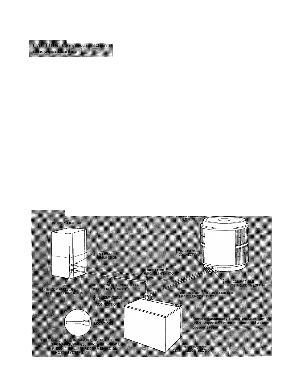
CONNECT REFRIGERANT LINES to fittings on
indoor and outdoor sections. Fig. 1, 2 and 5. Indoor
compressor section has 2 Compatible Fitting vapor
line connections. Outdoor and indoor fan-coil
sections have Compatible Fitting vapor line connec
tion and liquid line flare connection.
Flare and connect liquid line from outdoor coil
section to indoor fan-coil unit. It is not necessary
to flare system liquid line if an accessory flare-to-
Fig. 5 — Refrigerant Piping Connections
5