G-link connections, Networking units – ClearOne AP400 User Manual
Page 16
Installation
~ Networking Units
12
Technical Services Group ~ 1-800-283-5936 (USA) ~ 1-801-974-3760
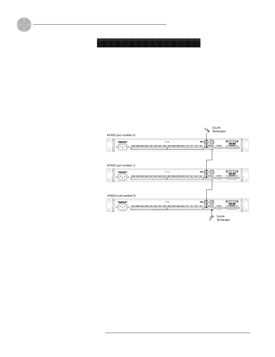
G-Link connections
Using the G-Link connectors, you can connect up to eight AP800/400s and 16 AP10
units, where the total number of microphone inputs does not exceed 64. Make
connections between units in daisy-chain fashion using the short RJ-45 jumper
(provided). If your units are further apart (maximum distance 20 feet), use category-
five twisted-pair cable (10 BaseT).
For a single-unit system, no connection is required in either G-Link In or
G-Link Out connectors.
To create a G-Link network
1.
Insert a G-Link terminator (provided) in the G-Link In connector of the first
unit in the network.
2.
Connect the RJ-45 jumper cable (or Cat. 5 twisted-pair cable) to the G-Link
Out connector of the first unit and to the G-Link In connector of the second
unit. Continue connecting units in the same fashion.
3.
Plug the G-Link terminator in the G-Link Out connector on the last unit to
complete the network connections.
A G-Link network supports
connection of a maximum
of any combination of 8
AP400s and AP800s. It also
supports up to 16 additional AP10s,
for a maximum of 24 telephone
lines.
✍
Figure 2.4. G-Link Network Connections
Networking Units