Winco ASCO 300 Accessory Connectivity Module User Manual
Page 3
iii Overview, Specifications, How to View Pages
Connectivity Module
Windows and Internet Explorer are registered trademarks of Microsoft Corporation.
Overview
The Connectivity Module brings together several
different serial devices that communicate at different
baud rates and with different protocols to a common
Ethernet media. It can communicate with up to eight
clients, such as Web applications (web pages), Vpi, or
third-party Modbus
®
devices simultaneously over
Ethernet media.
Specifications
Power Requirements: 24 V dc nominal (8 – 28 V dc)
1.5 Watt, UL Class 2 power supply, if needed.
Mounting:
35 mm DIN rail
Dimensions: 3.5” H, 2.8” W, 2.9” D (8.9 cm, 7.1 cm, 7.4 cm)
Field Communication Cable Requirements:
Ethernet:
Belden 7882A or equiv. UTP CAT 5 with
RJ45 connectors (untwisted pair or higher)
Serial:
Belden 9842, 9829, 89729, 82729 or Apha
6202C, 6222C, 58902. UL Listed, stranded,
twisted pairs, over-all foil shield with stranded drain wire
J1, J2 TTL Port Connectors:
Two built-in TTL ports
(DB9 pin male) for ATS/PM connectivity
J3 Ethernet Port Connector :
One built-in 10 Base T (RJ45) 10 Mbps Ethernet port
J4 Serial RS-485 Port:
One 5-pin terminal block header with a socket block (J4)
designed to be daisy chained for up to 32 devices.
Terminal 1 – RX+
Terminal 4 – TX-
Terminal 2 – RX-
Terminal 5 – Com
Terminal 3 – TX+
Ambient Temperature:
Operating
32 to 140° F (0 to 60° C)
Storage -
-40 to 185° F (-40 to 85° C)
Configuration Parameters: The parameters that are required
to make an Ethernet connection are:
IP Address
169.254.1.1
Subnet Mask
255.255.0.0
Gateway0.0.0.0
TCP Port No.
10001
The TCP port is used for passing the data to the applica-
tions and is configurable for user specific requirement.
Baud Rates
19200 (default) or 9600
Flow Control
No Flow Control (default)
Interface Mode TTL/RS485 – 4 wires (default)
Reply Timeout
200 milliseconds (default)
Protocol Support: The following protocols are supported:
Serial Protocol:
ASCO I, II, and Modbus
Transport Protocol:
TCP, UDP
Application Protocol: HTTP, Telnet, Modbus/TCP
How to View Pages from a Connectivity
Module after it is installed
After installation, testing, and configuration is completed
(see Section 1) to view pages on a client computer,
follow these steps:
1. Be sure that your computer is connected to the
Internet.
2. Start Microsoft Internet Explorer browser on the
computer.
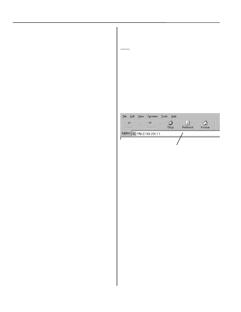
3. In the address bar, type in the address of the
Connectivity Module:
http://169.254.1.1
The Connectivity Module sends HTML files to the client
computer. Internet Explorer interprets these HTML
files, formats them, and displays the pages to the user.
Pages 2-3, 3-3, 4-2, 5-2, 5-3 shows typical HTML pages
(Detail screens).
Tip
You can add the address to your Favorites for
convenient access to multiple Connectivity
Modules; follow these steps:
1. Click Favorites, then click Add to Favorites,
click New Folder, then type the Folder name
(ATSs, for example), and click OK.
2. To rename the address, highlight it, and type the
new name, and click OK.
3. When you are finished viewing pages, close
Internet Explorer.
Type the address of the
Connectivity Module
h