Compaq AA-RHGWB-TE User Manual
Page 237
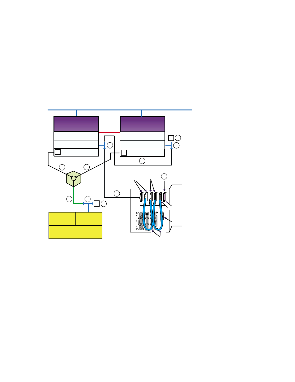
Figure 8–17: TL891 Standalone Cluster Configuration
KZPBA-CB (ID 7)
Memory
Channel
Interface
Memory Channel
KZPBA-CB (ID 6)
Memory Channel
Member
System
2
Member
System
1
DS-DWZZH-03
T
T
T
2
1
4
1
3
StorageWorks
RAID Array 7000
HSZ70
HSZ70
Controller B
Controller A
T
KZPBA-CB (ID 7)
5
5
6
7
KZPBA-CB (ID 6)
T
T
Network
T
NOTE: This drawing is not to scale.
Library
Robotics
Expansion
Unit
Interface
DLT1
TL891
DLT2
0.3 m
SCSI Bus
Jumper
6
7
ZK-1627U-AI
Table 8–12 shows the components used to create the cluster shown in
Figure 8–17.
Table 8–12: Hardware Components Used to Create the Configuration
Shown in Figure 8–17
Callout Number
Description
1
BN38C or BN38D cable
a
2
BN37A cable
b
3
H8861-AA VHDCI trilink connector
4
H8863-AA VHDCI terminator
5
BN21W-0B Y cable
Configuring a Shared SCSI Bus for Tape Drive Use 8–57
- Netelligent 8500 (3 pages)
- 127453-B21 (4 pages)
- AlphaPC 164LX (82 pages)
- QUICKSPECS 294162-B21 (1 page)
- PowerLeap JP2 (6 pages)
- 5900 (1 page)
- 517212-001 (26 pages)
- SmartCore Express SMA200 (42 pages)
- 212953-B21 (2 pages)
- NC3132 (4 pages)
- 705 (2 pages)
- au-Series (11 pages)
- AlphaPC 164SX (72 pages)
- 21264 (356 pages)
- PROLIANT 3000 (137 pages)
- ProLiant p-Class (24 pages)
- TL895 (10 pages)
- Microcom 420 (2 pages)
- uSign Signature Capture Module uSign 200 (18 pages)
- Universal Notebook Power Adapter SPS-2406 (4 pages)
- RAID ARRAY 3000 EK-SMCPO-UG. C01 (112 pages)
- DA-10121 (3 pages)
- AlphaStation XP1000 (16 pages)
- MICROSPACE MSEBX800 (53 pages)
- Contec RS-232C (77 pages)
- SDLT 220GB (8 pages)
- Cabinet H9A11 (32 pages)
- MTEK6000 (81 pages)
- SANetworks Network View DA10682 (6 pages)
- OXYGEN VX1 (29 pages)
- COM Express Extension (24 pages)
- Lithium-ion battery (7 pages)
- 164SX (72 pages)
- 3200 (211 pages)
- AA-Q88CE-TE (320 pages)
- MSB900L (66 pages)
- WL100 (2 pages)
- Wireless LAN 100 (2 pages)
- 1000 LX (4 pages)
- AAR-88LB-TE (42 pages)
- PC100 (66 pages)
- VAX 7000 Model 810 (9 pages)
- 99875320-5 (44 pages)
- CP-2E (91 pages)