Build the wing – Top Flite Sierra 40 Trainer Kit User Manual
Page 16
16
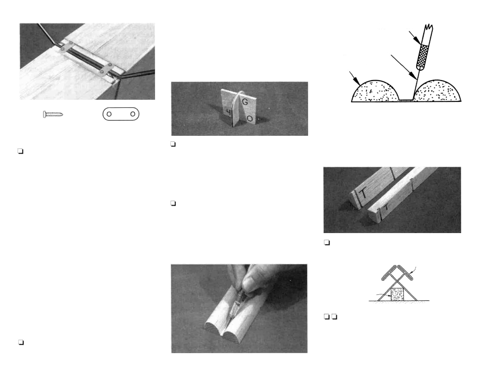
Nylon Landing Gear Strap
No. 2 x 3/8 Sheet
Metal Screw
46. Put the main landing gear back in position and
place two molded nylon landing gear straps over
the wire LG as shown in the picture. Mark, then drill
four 1/16" pilot holes. Use four No. 2 x 3/8" sheet
metal screws to hold down the LG straps. The
landing gear may be removed until after covering.
This completes the basic construction of the
fuselage.
BUILD THE WING
NOTE: The SIERRA wing, much like the fuse, is
designed so all the major components can be fit
together without glue. This allows you to check
that the pieces are properly fit and aligned before
applying glue to the joints. The wing plan may
be cut in half along the line provided if you wish.
1. Tape the LEFT WING PANEL portion of the
plan over your work surface. (The best work surface
is a very flat board that you can pin into. "Celotex,"
a type of board you can find at a hardware store or
home center, is an example of one). Cover the left
wing panel section with waxed paper so you won't
glue the wing to the plan.
2. Assemble the wing guide tool from the die-cut
1/8" plywood pieces marked "G". The "0" degree
(from vertical) side of the tool can be used to check
the ribs to see if they are vertical. The "4" degree
side will be used later. Do not glue the tool to-
gether.
3. The shaped and notched balsa leading edges
and trailing edges are joined by a thin layer of balsa.
These are cut apart in one of two ways:
A. Break the pieces apart and clean up the
rough edges with a sanding block.
-OR-
Hold knife at an angle
when cutting apart
LEADING EDGE
B. Carefully run a knife down the edge between
the parts to cut them cleanly apart.
NOTE: The Sierra was designed to use
symmetrical leading and trailing edges (they
have no top or bottom). They do, however, have
a root end and a tip end.
4. The tip ends of the leading and trailing edges
are the ends with a notch very close to the end. Mark
the leading and trailing edges with a "T" to designate
the tip. T-Pins
T-Pins
Spar
Work Surface
5. Use the criss-cross pin technique shown in
the illustration to pin a 3/8" x 3/8" x 30" balsa spar
over its location on the plans. Pin the spar in 3 or 4
places. (The photo for this step is at the top of the
next column)
Xacto knife