Top Flite TOPA0950 User Manual
Page 22
22
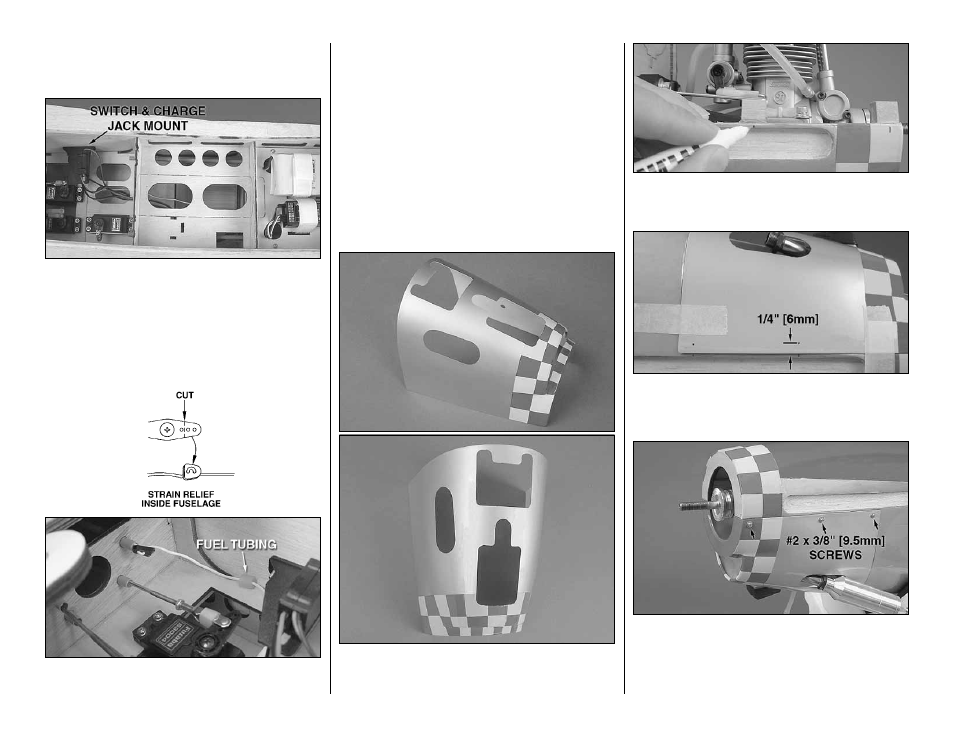
using four #2 x 3/8" [9.5mm] self-tapping screws and
four #2 fl at washers. Be sure to harden the screw
holes with thin CA.
❏
3. Install your receiver switch onto the side of the
fuselage opposite the muffl er and in a location that
will not interfere with any of the servos. We used a
Great Planes Switch and Charge Jack Mounting Set
(GPMM1000). Connect your servos and switch to the
receiver and connect the receiver battery to the switch.
Be sure to use tape or heat shrink tubing to secure the
connection between the switch and the battery.
❏
4. Install a strain-relief onto the receiver antenna
and route it through the antenna tube and out the
back of the fuselage. We used a small piece of fuel
tubing glued to the side of the fuselage to hold the
antenna out of the way of the elevator servo.
FINISH THE MODEL
INSTALL THE COWL
❏
1. If you haven’t done so already, connect the fuel
pickup line to the needle valve on the engine and cut
the fi ll line and pressure line to the proper length. An
aluminum fuel line plug is provided for the fi ll line.
❏
2. Make the necessary cutouts in the cowl to match
your engine. In the picture, there is an opening for the
engine head, muffl er, cooling hole, and needle valve.
❏
3. Use a felt-tip pen to mark the middle of each
cowl mounting block just outside the cowl line on
the fuselage.
❏
4. Tape the cowl into position with masking tape.
Transfer the marks you made in step 3 onto the cowl
1/4" [6mm] inside the cowl edges.
❏
5. Drill through the marks on the cowl with a 1/16"
[1.6mm] drill bit. Remove the cowl and enlarge the
holes in the cowl with a 3/32" [2.4mm] bit. Thread a
#2 x 3/8" [9.5mm] self-tapping screw into each cowl
mounting block and remove it. Apply a couple drops of