Top Flite TOPA0950 User Manual
Page 17
position of the stab, use a felt tip marker to mark the
outline of the fuselage onto the top and bottom of it.
❏
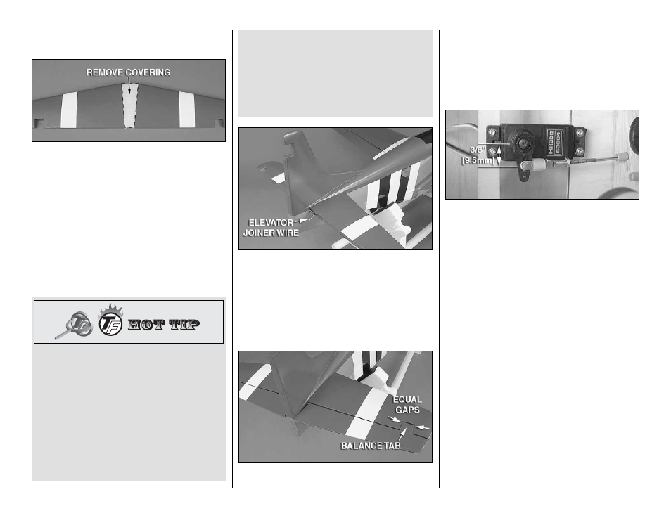
5. Remove the elevators and horizontal stab from
the fuselage. Remove the covering from both sides
of the stab 1/16" [1.6mm] inside the lines you drew.
Wipe away the lines with denatured alcohol.
❏
6. Unhook the clevises from the servo arm and
elevator control horn. Remove the pushrod from the
fuselage. Cut the pushrod to length and solder the
clevis onto the cut end using your mark as a guide.
Install a silicone clevis retainer onto the solder clevis.
Remove the threaded clevis and 2-56 nut from the
other end of the pushrod and insert the threaded end
of the pushrod through the aft end of the elevator
pushrod tube up to the elevator servo.
How To Solder The Clevis To The Pushrod
1. Where the pushrod will make contact with the solder
clevis, roughen the wire with 220-grit sandpaper.
2. Use denatured alcohol to remove any oil residue
from the pushrod wire.
3. Apply a couple of drops of fl ux to the wire. Slide
the solder clevis onto the wire. Using a small
torch or soldering iron, heat the wire allowing
the heated wire to heat the solder clevis. Apply
a small amount of solder to the joint. When the
wire and the clevis are hot enough the solder will
fl ow into the joint. Avoid using too much solder
causing solder to fl ow out of the joint and clump.
Use just enough solder to make a good joint.
Allow the wire and clevis to cool.
4. Put a couple of drops of oil onto a rag and wipe the
joint. This will prevent rust from forming on the joint.
❏
7. Being sure that the elevator joiner rod is still in
position in the stab saddle, use 30-minute epoxy to
glue the stab into the fuselage being sure the stab is
correctly positioned in the stab saddle. Wipe away any
excess epoxy with denatured alcohol and let the epoxy
cure undisturbed.
IMPORTANT: Make sure you reinstall the elevator
pushrod, see step 6.
❏
8. Roughen the ends of the elevator joiner rod and
clean them with alcohol. Insert CA hinges into the
elevator hinge slots. Apply a light coating of epoxy to
the ends of the joiner rod and join the elevators to the
stab with the hinges. Be sure that the balance tabs
on the elevators are centered in the cutouts. When
satisfi ed, apply thin CA to the top and bottom of each
hinge to secure the elevators in place. Wipe away any
excess epoxy from around the joiner rod.
❏
9. Connect the solder clevis to the outer hole in the
elevator control horn of the elevator joiner wire and
slide the silicone clevis retainer to the end of the clevis.
Thread a 2-56 nut and threaded clevis back onto the
pushrod along with a silicone clevis retainer. Make
any adjustments necessary to the clevis so that the
elevators are in the neutral position when the servo
arm is perpendicular to the servo case. When satisfi ed,
attach the clevis to the second hole from the center of
the servo arm, tighten the 2-56 nut against the back of
the clevis with threadlocking compound, and slide the
silicone clevis retainer to the end of the clevis.
17