Top Flite TOPA0950 User Manual
Page 18
18
INSTALL THE RUDDER, TAIL WHEEL
& LINKAGES
❏
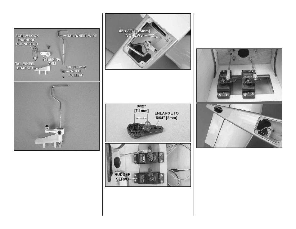
1. Locate the pieces for the tail wheel assembly.
Loosely thread the 3 x 5mm SHCS into the collar
hole in the steering arm. Slide the steering arm onto
the tail wheel wire and tighten the SHCS against the
fl at spot in the wire. Be sure that the steering arm is
oriented in the same direction as shown in the picture.
Slide the tail wheel bracket onto the wire beneath the
steering arm. Tighten a 1/8" [3.2mm] wheel collar
using a 4-40 set screw onto the wire below the tail
wheel bracket. The bracket should still be able to
rotate freely on the wire. Secure a brass screw-lock
pushrod connector to the linkage hole in the steering
arm with a nylon retainer. Loosely thread a 4-40 set
screw into the screw-lock pushrod connector.
❏
2. Coat the barbed posts on the underside of the tail
wheel bracket with epoxy or thick CA. Insert the posts
into the receiving holes in the tail wire access hatch in
the fuselage. The end of the tail wire will fi t into a bushing
that is pre-installed in the fuselage. Secure the assembly
with two #2 x 3/8" [9.5mm] self-tapping screws.
❏
3. Cut three arms from a four-armed servo arm
included with the rudder servo. Enlarge the second
to outer hole with a 5/64" [2mm] drill bit. Install a
.080" ball stud into the inner hole of the servo arm
and secure it with a .080" nut with threadlocking
compound. Center the servo with your radio system
and install the servo arm perpendicular to the servo
case. Secure the servo arm with the servo arm screw.
Place the servo onto the servo tray in the fuselage
in the position shown with the servo spline facing
forward. Attach the servo to the tray with the hardware
included with the servo. Be sure to harden the screw
holes with thin CA.
❏
4. Thread a nylon ball cup onto the end of a 2-56
x 36" [914mm] threaded one-end pushrod. Insert the
pushrod into the pushrod tube in the fuselage that
is inline with the ball stud (closest to the bottom of
the fuselage) on the servo arm. Feed the aft end of
the pushrod through the brass screw-lock pushrod
connector on the tail wire steering arm and out the
elevator control horn access hole. Push the ball cup
onto the ball stud.
❏
5. Center the tail wheel wire axle in the neutral
position and tighten the set screw in the screw-lock
pushrod connector against the tail wheel pushrod. Cut
off the excess pushrod 1/2" [13mm] behind the screw-
lock pushrod connector.