Top Flite TOPA0708 User Manual
Page 9
9
HOW TO SOLDER
1. Roughen the end of the pushrod with coarse
sandpaper where it is to be soldered. Use denatured
alcohol or other solvent to thoroughly clean the
pushrod.
2. Apply a few drops of soldering fl ux to the end of
the pushrod, then use a soldering iron or a torch
to heat it. “Tin” the heated area with silver solder
by applying the solder to the end. The heat of the
pushrod should melt the solder – not the fl ame of
the torch or soldering iron – thus allowing the solder
to fl ow. The end of the wire should be coated with
solder all the way around.
3. Place the clevis on the end of the pushrod. Add
another drop of fl ux, then heat and add solder. The
same as before, the heat of the parts being soldered
should melt the solder, thus allowing it to fl ow. Allow
the joint to cool naturally without disturbing. Avoid
excess blobs, but make certain the joint is thoroughly
soldered. The solder should be shiny, not rough. If
necessary, reheat the joint and allow to cool.
4. Immediately after the solder has solidifi ed, but
while it is still hot, use a cloth to quickly wipe off
the fl ux before it hardens. Important: After the joint
cools, coat the joint with oil to prevent rust. Note: Do
not use the acid fl ux that comes with silver solder for
electrical soldering.
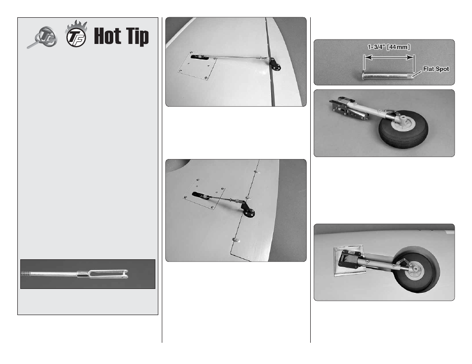
This is what a properly soldered clevis looks
like – shiny solder with good flow, no blobs and
flux removed.
❏
❏
4. Slide a silicone clevis retainer over the solder
clevis. Reinstall the aileron pushrod with the threaded
clevis attached to the control horn. Adjust the threaded
clevis so that the aileron is centered. Apply a drop of
thread locker to the threads of the pushrod behind the
clevis. Tighten the 4-40 nut against the clevis.
❏
❏
5. Assemble and connect the fl ap pushrods
following the same procedure, except, adjust the fl ap
control on your transmitter to the fl ap up position. Position
the fl aps in the up position. We installed the pushrod
in the outer hole of the control horn and the hole 5/8"
[16mm] from the center of the servo arm. Use #4 x ½"
sheet metal screws in the forward holes and #4 x 3/8"
sheet metal screws in the aft holes.
❏
6. Return to step 1 and install the aileron and fl ap
pushrods on the right wing.
MOUNT THE RETRACTS
Install the left retract fi rst.
❏
❏
1. Trim the axle that is included with the Robart
retracts to 1-3/4" [44mm] long. File a fl at spot at the
end of the axle. Insert the axle through the included 5"
[127mm] wheel. Insert the axle into the retract. Apply
a drop of threadlocker to the 10-32 x 3/16" [4.8mm]
set screw, included with the retract, and tighten the
set screw onto the fl at of the axle. Make sure that the
wheel rotates freely.
❏
❏
2. Test fi t the retract unit with the wheel into the
wing. Position the retract so the wheel is centered in
the wheel well. Adjust the strut position in the retract
body as necessary to achieve the correct spacing all
the way around the wheel.