Top Flite TOPA0708 User Manual
Page 8
8
secure the servo mounting blocks to the aileron servo
hatch. Use thin CA to harden the screw threads
❏
❏
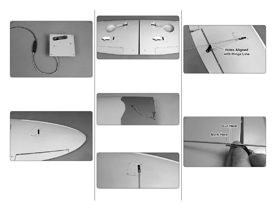
7. Connect a 24" [610mm] servo extension wire
(not included) to the aileron servo. Cut a piece of the
included heat shrink tubing in half and slide it over the
servo connections. Shrink the tubing by applying heat.
❏
❏
8. Use the string in the wing to pull the aileron
wire through the wing.
❏
❏
9. Place the aileron servo hatch with the servo
in the wing. Be certain that the hatch is positioned
correctly as shown. Secure the hatch using four #2 x
3/8" [9.5mm] sheet metal screws and #2 fl at washers.
Use thin CA to harden the screw threads.
❏
10. Go back to step 1 and install the right aileron servo
following the same procedure. Firmly pull on the ailerons
and fl aps to check that the hinges are securely glued.
INSTALL THE FLAP SERVOS
❏
❏
1. Install the fl ap servos following the same
procedure used to install the aileron servos. Note that
the fl ap servos face the same direction.
❏
❏
2. Connect a 12" [304mm] servo extension wire to
the fl ap servo. Secure the extension to the servo with
a piece of heat shrink or electrical tape.
❏
❏
3. Route the fl ap and aileron servo leads to the
root of the wing and out the hole in the top of the wing.
INSTALL THE AILERON AND FLAP PUSHRODS
Do the left aileron fi rst.
❏
❏
1. Slide a silicone clevis retainer over a 4-40
threaded metal clevis. Thread a 4-40 nut followed by
the 4-40 metal clevis, threaded 12 turns onto a 4-40
x 12" [304mm] metal pushrod. Attach the clevis to the
aileron servo arm 5/8" [16mm] from the center of the arm.
❏
❏
2. Position the control horn so that it is in line with
the pushrod and over the plywood mounting plate. The
pushrod holes in the control horn should be aligned
with the hinge line of the aileron. On the aileron, mark
the four mounting holes. Remove the control horn and
drill a 5/64" [2mm] pilot hole at each mark. Do not drill
completely through the aileron. Attach the control horn
using four #4 x ½" sheet metal screws. Use thin CA to
harden the holes.
❏
❏
3. Install the metal solder clevis in the hole at the
end of the control horn. Center the aileron servo and
aileron. Mark the pushrod where it meets the solder
clevis. Remove the pushrod and the solder clevis and
cut the pushrod ¼" [6.4mm] past the mark. Solder
the solder clevis to the pushrod using the techniques
described in the following Hot Tip.